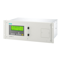
The positions of the connections on the devices are shown in the connection diagrams in section
Connection diagrams (Page 51).
3.5.3 Connection diagrams
Bench-top unit
① Power connector
② Gas connections: 6 mm nozzles; see section Gas connections (Page 50)
③ -X45: ELAN (RS485) 9-pin connector
④ -X90: 9-pin interface connector (option board with PROFIBUS-DP/PA)
⑤ -X50: 37-pin connector: Option board; binary inputs/relay outputs
⑥ -X80: 37-pin connector: Analog and digital inputs and outputs
Figure 3-18 Connections of bench-top unit
Description
3.5 Wiring diagrams
ULTRAMAT 23
Equipment Manual, 04/2022, A5E37100388-012 51

 Loading...


