7.4.1 Warm-up phase
,QSXWPRGH
0HDVPRGH
:DUPXSPRGH
(17(5
75
ᆚᆚᆚᆚᆚᆚᆚᆚᆚᆚᆚᆚᆚᆚᆚᆚᆚᆚᆚᆚ
ᆚᆚᆚᆚᆚᆚᆚᆚᆚᆚᆚᆚᆚᆚᆚᆚᆚᆚᆚᆚ
ᆚᆚᆚᆚᆚᆚᆚᆚᆚᆚᆚᆚᆚᆚᆚᆚᆚᆚᆚᆚ
ᆚᆚᆚᆚᆚᆚᆚᆚᆚᆚᆚᆚᆚᆚᆚᆚᆚᆚᆚᆚ
74
403.8 vpm CO |
1875 vpm NO |
936.4 vpm SO2 |
4.4 % O2 |
Analyzer status
Calibration
Parameters
Configuration
Warm-up mode
Time left 02:02 min
73a
73b
AUTOCAL
Time left 01:44 min
Purging w. CAL gas
73c
AUTOCAL
Time left 01:44 min
Purging w. meas.gas
73d
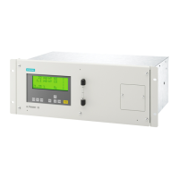
Figure 7-4 Warm-up phase, measuring mode, and input mode
73a
ᆚᆚᆚᆚᆚᆚᆚᆚᆚᆚᆚᆚᆚᆚᆚᆚᆚᆚᆚᆚ
ᆚᆚᆚᆚᆚᆚᆚᆚᆚᆚᆚᆚᆚᆚᆚᆚᆚᆚᆚᆚ
ᆚᆚᆚᆚᆚᆚᆚᆚᆚᆚᆚᆚᆚᆚᆚᆚᆚᆚᆚᆚ
ᆚᆚᆚᆚᆚᆚᆚᆚᆚᆚᆚᆚᆚᆚᆚᆚᆚᆚᆚᆚ
Immediately following switching-on, the ULTRAMAT 23 tests the
display elements. During this test, all elements light up simulta‐
neously for approx. ve seconds.
Warn-up mode
Time left 02:02 min
73b
The adjacent display subsequently appears with the remaining
warm-up period which is counted down in seconds to 00:00
(minutes:seconds).
In the rst 5 minutes of the warm-up phase, the 4 mA value is
always transferred over the analog interface and the 'Function
control (FCTRL)' status is set. This does not represent an error.
Operation
7.4 Operating modes
ULTRAMAT 23
Equipment Manual, 04/2022, A5E37100388-012 93

 Loading...


