Connecting
5.3 Electrical connection
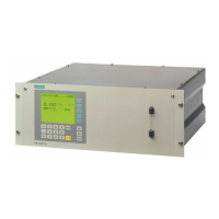
ULTRAMAT 23
74 Manual, 3/2016, A5E37100388-003
● The connection lines to the relay outputs, binary inputs, and analog outputs must be
shielded.
● The analog outputs are floating, but have a common negative pole.
● As a measure to suppress sparking across the relay contacts (e.g. limit relays), RC
elements must be connected as shown in the following figure. Note that the RC element
results in a drop-out delay for an inductive component (e.g. solenoid valve). The RC
element should be sized according to the following rule of thumb:
– R = R
L
/2; C = 4L/R
2
L
,
where R = 100 Ω and C = 200 nF are sufficient.
– You must use a non-polarized capacitor for the RC element.
Figure 5-2 Measure to suppress sparks on a relay contact
When operated with direct current, a spark suppression diode can be installed instead of the
RC element.
Connect the signal lines to the Sub-D plugs at the rear of the device.
Refer to the ELAN interface description (Order No. C79000-B5200-C176 German, C79000-
B5276-C176 English) for details on the interface cable.
Check before connecting that the existing supply voltage corresponds to that specified on
the label of the device.
Install the power line separately from the signal lines.

 Loading...