45
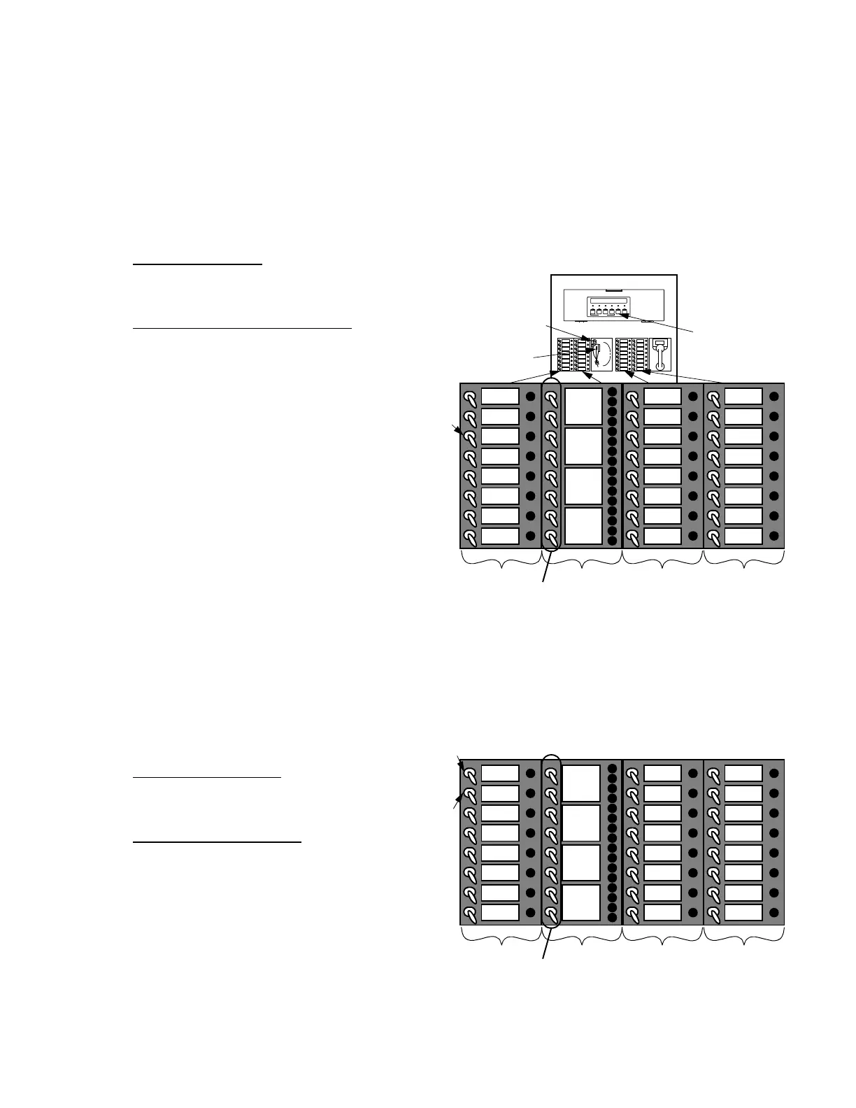
HOW TO OPERATE THE MICROPHONE DURING AUTOMATIC ALARM CONDITIONS (SEE FIGURE 22)
You can silence ALARM/EVAC signals by pressing the <ALARM SILENCE> key on the interface panel. This action
stops the Voice Tone Generator (VTG). To use the microphone, you must manually select desired speaker circuits
with the individual Speaker Select Switches, the ALL SPEAKERS TALK switch, or the optional ALL SPEAKERS
MINUS switch.
During automatic alarm conditions, operate the microphone in the following manner.
1. Press the <ALARM SILENCE> key to turn OFF the alarm signals/ messages, if desired.
NOTE: To talk to all areas in alarm, go to Step 3.
Figure 22
LED/Switch Locations for Microphone Operation
During Alarm Conditions (Triple Channel)
ALL
SPEAKERS
EVAC
SELECTIVE
EVAC
ALL
SPEAKERS
TALK
A
PHONE
PHONE 1
PHONE 2
PHONE 7
PHONE 8
PHONE 9
PHONE 10
PHONE 15
SILENCE
PHONE 3
PHONE 4
PHONE 5
PHONE 6
PHONE 11
PHONE 12
PHONE 13
PHONE 14
C
D
ALARM
SILENCE
B
OPERATION SELECT
SWITCHES
SPEAKER SELECT
SWITCHES
PHONE SELECT
SWITCHES
PHONE SELECT
SWITCHES
EVAC
ALERT
TALK
TBL
EVAC
ALERT
TALK
TBL
EVAC
ALERT
TALK
TBL
EVAC
ALERT
TALK
TBL
F
L
R
1
F
L
R
2
F
L
R
3
F
L
R
4
LOCAL
SPEAKER
EVAC
LOCAL
SPEAKER
ALERT
HOW TO MANUALLY INITIATE AN EVACUATION SIGNAL (SEE FIGURE 23)
2. To talk to ALL areas:
Turn ON (UP) the ALL SPEAKERS TALK
Switch (Item A) and go to Step 3.
To talk to ALARM/SPECIFIC areas:
Turn desired bottom Speaker Select Switch
either UP to activate or DOWN to de-activate
(Item B).
3. Remove the microphone from the cradle; press
the Talk switch (Item C). Wait for the green
TALK LED to turn ON (Item D).
4. Make the appropriate announcement.
5. When finished, unkey the microphone and
place it in the cradle. In an Alarm condition,
unkeying the mike may play a pre-selected
tone over the speaker circuits which are still
selected.
6. Turn OFF (DOWN) the ALL SPEAKERS TALK
Switch (Item A) and return all activated
Speaker Select Switches (Item B) to center
position.
To manually initiate an evacuation signal, do the
following.
1. To evacuate ALL areas:
Turn ON (UP) the ALL SPEAKERS EVAC
Switch (Item A).
To evacuate specific areas:
a. Turn ON (UP) the desired Speaker Select
Switches (Item B).
b. Turn ON (UP) the SELECTIVE EVAC
Switch (Item C).
2. To turn OFF all speaker circuits, turn OFF
(DOWN) the ALL SPEAKERS EVAC Switch
(Item A).
Figure 23
LED/Switch Locations for Evacuation Signal
Initiation (Triple Channel)
ALL
SPEAKERS
EVAC
SELECTIVE
EVAC
LOCAL
SPEAKER
ALERT
EVAC
A
PHONE
PHONE 1
PHONE 2
PHONE 7
PHONE 8
PHONE 9
PHONE 10
PHONE 15
SILENCE
PHONE 3
PHONE 4
PHONE 5
PHONE 6
PHONE 11
PHONE 12
PHONE 13
PHONE 14
B
OPERATION SELECT
SWITCHES
SPEAKER SELECT
SWITCHES
PHONE SELECT
SWITCHES
PHONE SELECT
SWITCHES
C
LOCAL
SPEAKER
EVAC
ALERT
TALK
TBL
EVAC
ALERT
TALK
TBL
EVAC
ALERT
TALK
TBL
EVAC
ALERT
TALK
TBL
F
L
R
1
F
L
R
2
F
L
R
3
F
L
R
4