61
ACTION KEYS
There are six action keys on the DISPLAY/ACTION keypad (see Figure 37):
• Disable (Refer to Section 1, “How to Disable a Point”)
• Enable (Refer to Section 10, “How to Enable a Disabled Point”)
• Off (Refer to Section 10, “How to Turn a Point OFF”)
• On (Refer to Section 10, “How to Turn a Point ON”)
• Auto (Refer to Section 10, “How to Return a Point to Auto”)
• Display Time (Refer to Section 1, “Using the <DISPLAY TIME> Key”)
ENTRY KEYPAD
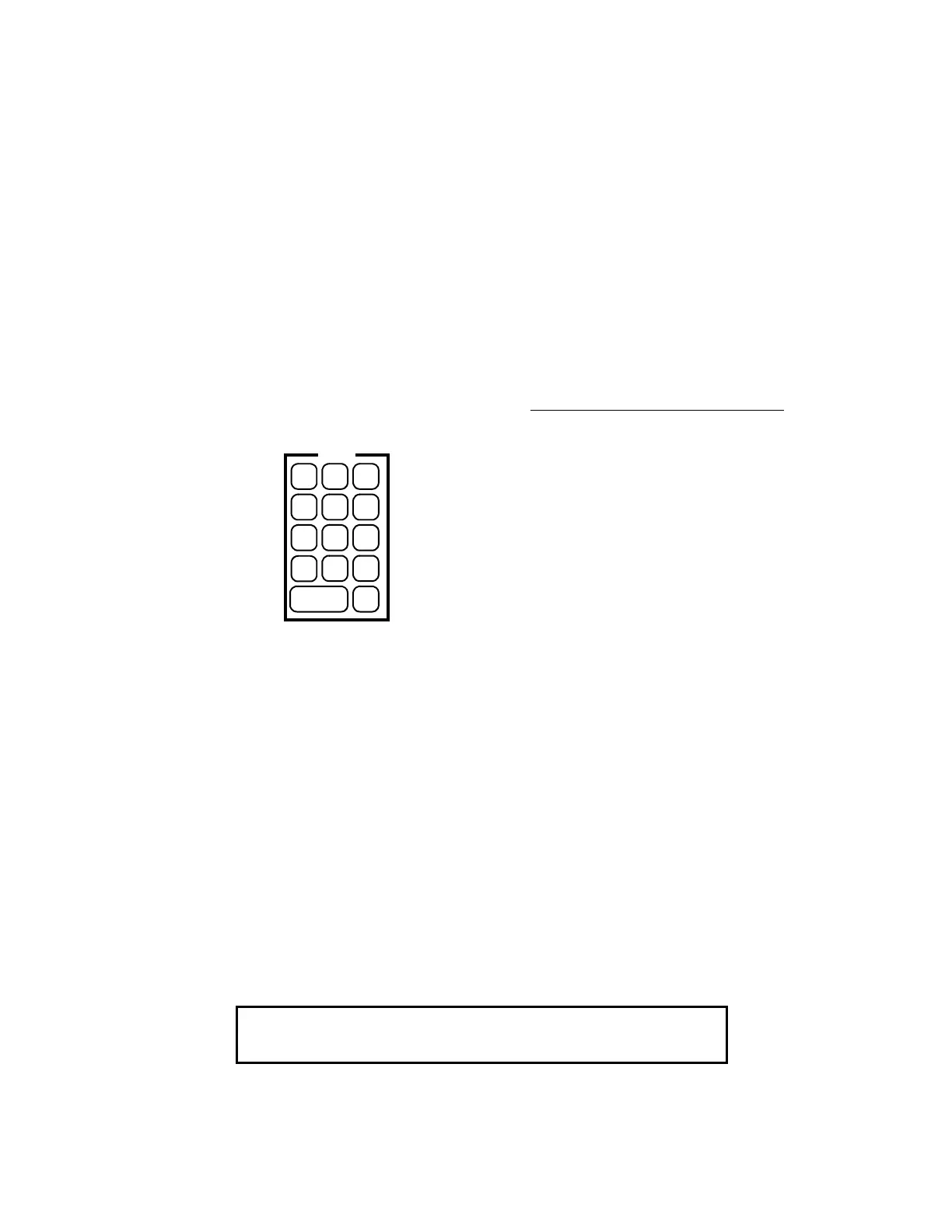
The ENTRY Keypad is located to the far right on the interface panel and is concealed by the access door. There are
fourteen keys on this keypad (Figure 38).
Figure 38
ENTRY Keypad
These keys are used to enter passcodes, identifiers, or numeric data for the system. Whenever the system expects
numeric data input, the user is notified with a prompt. Numeric data input requires an <ENTER> key press to
complete the keypad entry. Numeric keys also double as “prefix” keys. When entering a point, a prefix key must be
used to identify how the entry is made. Pressing the zone key (key 1) indicates that the next numeric entry is a zone
number. Pressing the address key (key 0) indicates that an address identifier is entered.
HOW TO USE PREFIX KEYS TO DISPLAY SYSTEM POINTS
The first key press from the ENTRY keypad must be a prefix key press. The prefix selects either monitor points,
signal points, auxiliary points, feedback points, graphic input/output points, MAPNET II
points, digital pseudo
points, analog pseudo points, list pseudo points, network points, or point address format. In response to the first key
press, the type of input requested is displayed. The display below shows a zone input for the first key press (key 1
for this example).
1 = Monitor Zone #
2 = Signal Zone #
3 = Auxiliary Zone #
4 = Feedback Zone #
5 = I/O Zone (Point)#
6 = MAPNET II
Point #
7 = Digital Pseudo Point #
8 = Analog Pseudo Point #
9 = List Pseudo Point #
0 = Numeric System Address #
NUMERIC KEY DESCRIPTION
ENTRY
ZONE SIG AUX
FB I/O MAP
PAL
ADDR
DEL
CLR
1
4
7
_
ENTER
2
5
8
0
3
6
9
NET
Please input a ZONE number
MONITOR ZONE: ZN