42
TRIPLE CHANNEL AUDIO OPERATIONS
The following paragraphs discuss 4100 Triple Channel Audio Operations.
AUDIO CONTROL LED/SWITCH MODULE FOR TRIPLE CHANNEL AUDIO
The Audio Control Module contains eight switches and LEDs. The LED next to each switch illuminates to indicate
that an operation controlled by that switch has been selected. Figure 21 shows a Triple channel Audio Control LED/
Switch Module controlling the following functions:
• ALL SPEAKERS EVAC
• SELECTIVE EVAC
• ALL SPEAKERS TALK
• LOCAL SPEAKER ALERT
• LOCAL SPEAKER EVAC.
The function of each switch is explained in the following paragraphs.
Figure 21
Audio Control Led/Switch Module for Triple Channel Operations
ALL
SPEAKERS
EVAC
SELECTIVE
EVAC
ALL
SPEAKERS
TALK
LOCAL
SPEAKER
ALERT
LOCAL
SPEAKER
EVAC
TRIPLE CHANNEL
ALL SPEAKERS EVAC
SELECTIVE EVAC
ALL SPEAKERS TALK
(BLANK)
(BLANK)
(BLANK)
LOCAL SPEAKER ALERT
LOCAL SPEAKER EVAC
AUDIO CONTROL
SWITCH MODULE
TRIPLE CHANNEL
Figure 20
LED/Switch Locations for Microphone Operation
During Non-Alarm Conditions (Dual Channel)
ALL
SPEAKERS
EVAC
SELECTIVE
EVAC
ALL
SPEAKERS
TALK
LOCAL
SPEAKER
FLR 1
FLR 2
FLR 3
FLR 8
FLR 4
FLR 5
FLR 6
FLR 7
A
PHONE
PHONE 1
PHONE 2
PHONE 7
PHONE 8
PHONE 9
PHONE 10
PHONE 15
SILENCE
PHONE 3
PHONE 4
PHONE 5
PHONE 6
PHONE 11
PHONE 12
PHONE 13
PHONE 14
C
D
B
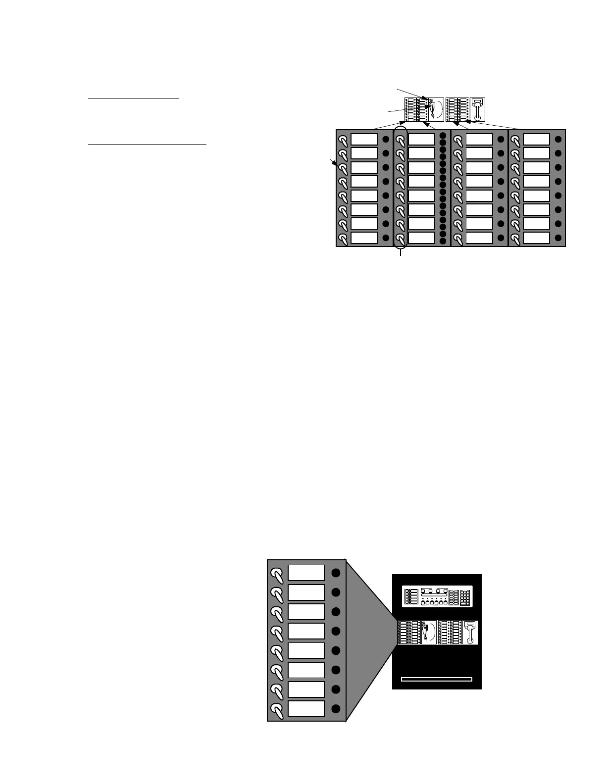
HOW TO OPERATE THE MICROPHONE DURING NON-ALARM CONDITIONS (SEE FIGURE 20)
During non-alarm conditions, operate the microphone in the
following manner.
1. To talk to ALL areas:
Turn ON (UP) ALL SPEAKERS TALK Switch (Item A)
and go to Step 2.
To talk to SPECIFIC areas:
Turn desired Speaker Select Switches DOWN to
activate (Item B).
2. Remove the Microphone from the cradle; press the
Talk switch (Item C). Wait for the green TALK LED to
turn ON (Item D).
3. Make the appropriate announcement.
4. When finished, unkey the Microphone and place it in
the cradle.
5. Turn OFF (DOWN) ALL SPEAKERS TALK Switch
and/or activated Speaker Select Switches to
CENTER position (Items A and B).