Simrad AP50 Autopilot
104 20221032B
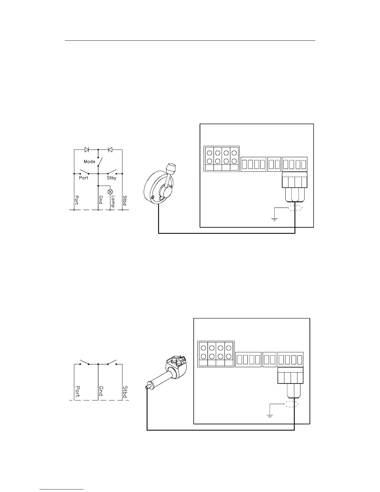
4.18 S35 NFU Steering Lever
The S35 NFU Steering Lever may be mounted to the bulkhead
or to a panel by two screws from the front. The cable is
connected to the junction unit according to Figure 4-31. If
necessary, interchange the Port and Stbd wires to the screw
terminals in the junction unit to make the direction of the lever
movement coincide with the direction of the rudder movement.
S35
STEERING LEVER
NOTE!
Disregard the color code
on the terminal label.
REMOTE
JUNCTION UNIT
POWER PCB
TB1
TB2
TB3
TB5
Brn/Wh
Pnk/Gry
Grn
REMOTE
TB4
Yel
Stbd
Port
Gnd
Lamp
Figure 4-31 S35 NFU Steering Lever Connection to Junction Unit
The steering lever is opened by removing the three screws on
the back cover. Inside are two sets of micro-switches, a printed
circuit board with a plug-in terminal, and a jumper strap.
4.19 F1/2 Remote Control
The F1/2 Remote Control comes with 10 m (33 ft.) of cable and
is connected to the junction unit as shown in Figure 4-32.
F1/2
REMOTE CONTROL
NOTE!
Disregard the color code
on the terminal label.
REMOTE
JUNCTION UNIT
POWER PCB
TB1
TB2
TB3
TB5
Violet
Brown
Beige
REMOTE
TB4
Stbd
Port
Gnd
Figure 4-32 F1/2 Remote Control Connection