Installation
20221032B 93
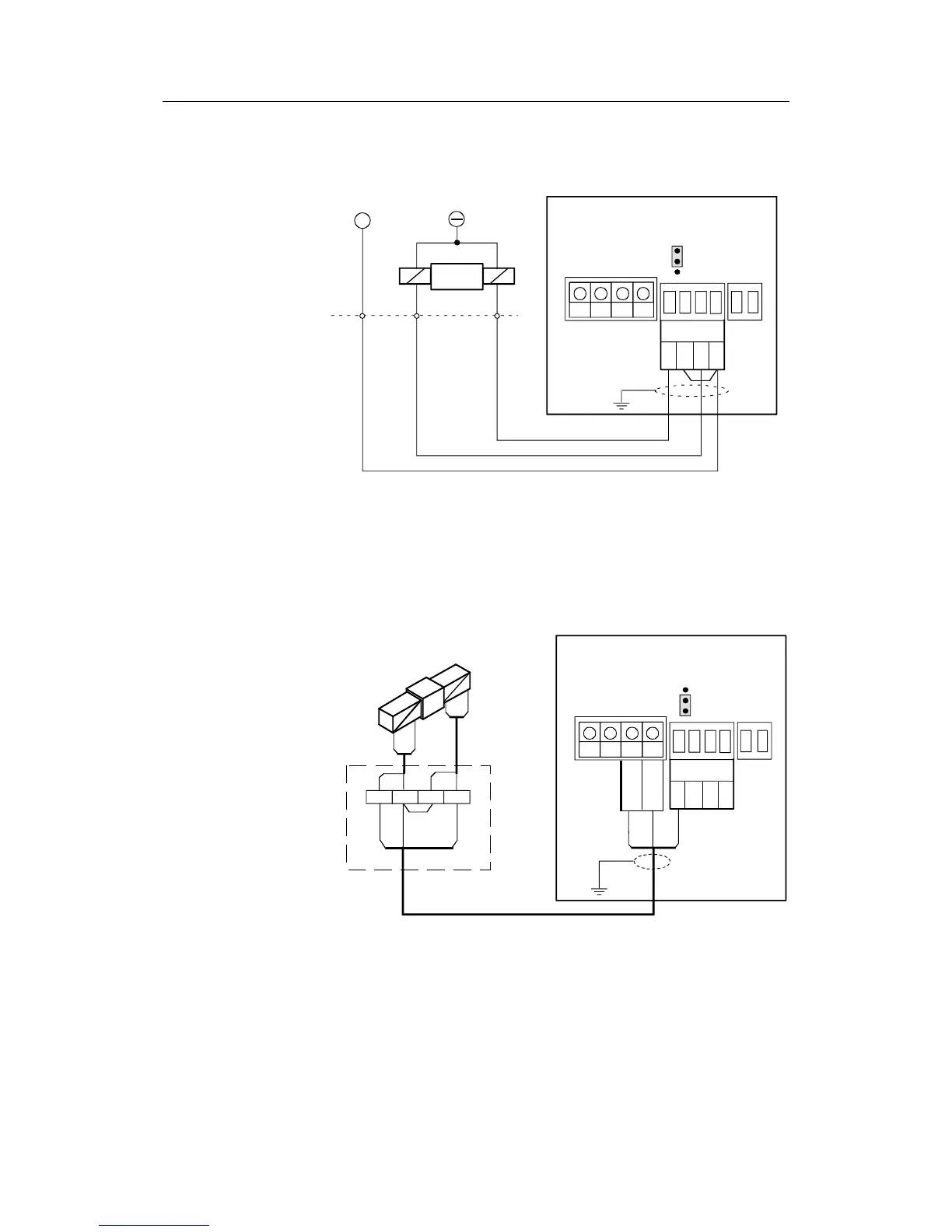
Solenoids (externally powered, common
negative)
JUNCTION UNIT
POWER PCB
TB1
TB2
TB3
TB4
Solenoid
isolated
Lo1
Hi1
Lo2
Hi2
1
2
3
S1
+
SOLENOID
VALVE
Figure 4-18 Connecting Externally-powered Solenoids with
a Common Negative
Caution ! To prevent damage of the J50 Power PCB, ensure that the S1
jumper switch on the Power PCB is set to position 2-3.
Solenoids (not externally powered)
JUNCTION UNIT
POWER PCB
Sol. Sol.Lo1
SOLENOID
VALVE
TB1
TB2
TB3 TB4
Sol. -Motor
Sol. -Motor
Solenoid
isolated
Lo1
Hi1
Lo2
Hi2
1
2
3
S1
Figure 4-19 Connecting Non-powered Solenoids
Note ! The jumper switch S1 on the J50 Power PCB must be set to
position 1-2.