Installation
20221032B 109
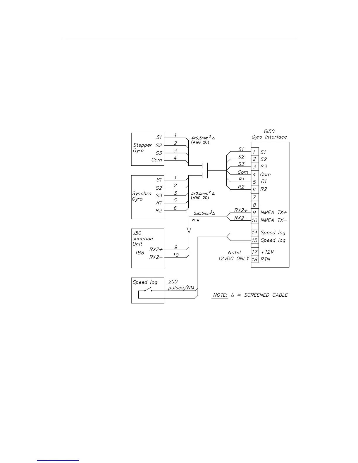
GI50 Gyro Interface
The GI50 Gyro Interface is required when a gyrocompass with
geared synchro or stepper signal output is connected to the
AP50.
The GI50 is also required when a speed log signal with 200
pulses/NM is connected to the system.
All cable conductors are terminated in screw terminals on the
GI50 PCB. For cabling and connections, see Figure 4-39.
Figure 4-39 GI50 Gyro Interface Connections
There are also three plug-in jumpers on the PCB, one for each
phase. The position of the jumpers allows the GI50 to operate
from either positive or negative step-signals. For setting of the
jumpers, refer to Figure 4-40. The shown jumper position
enables step-signals with positive common. For negative
common, insert jumpers vertically, A1-A3, A2-A4 and so on.
In addition, a DIP switch is included. Switch number 1 sets the
gear ratio: 360:1 + stepper = switch to 0 (OFF), 90:1 = switch to
1 (ON)
The remaining switches 2, 3, and 4 are for test purpose only and
should be 0 (OFF) for normal use. Figure 4-40 shows the
location of the switches and the LED's.