Installation
20221032B 85
4.9 J50 Junction Unit
The J50 Junction Unit is designed to operate in a location that
provides ambient temperatures below +55°C (+130°F).
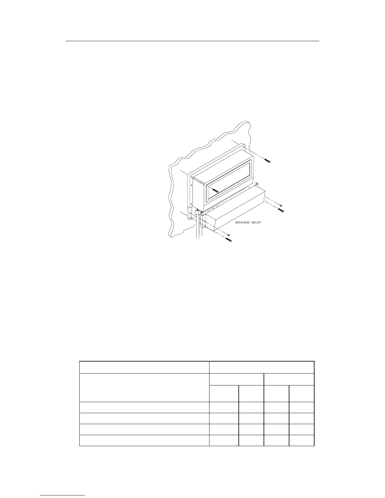
Note ! The junction units (J50 and J50-40) are not waterproof and
should be mounted vertically, as shown in Figure 4-11, in a dry
place between the control unit and the drive unit.
Figure 4-11 J50 Junction Unit Mounting
Cable Connections
Use only shielded cables. This includes Mains input, drive units,
and, if necessary, for the extension of the RF300S Rudder
Feedback Unit cable. The clutch/bypass cable and the solenoid
cable should be 1.5 mm
2
(AWG14). Signal cables should be 0.5
mm
2
(AWG20) twisted-pairs.
The Mains supply cable and the drive unit motor cable should
have sufficient wire gauge. This will minimize voltage drop and
allow the drive unit to operate at full power.
Refer to the table below for recommended cable sizes.
Cable length Drive Unit Voltage
1. Distribution Board to Junction Unit. 12 V 24 V
2. Junction Unit to Drive Unit motor
(Length refers to each of the two cables)
mm
2
AWG mm
2
AWG
Up to 3 m (10 ft.) 2,5 12 2,5 12
Up to 6 m (20 ft.) 4 10 2,5 10
Up to 10 m (32 ft.) 6 8 4 10
Up to 16 m (52 ft.) 10 6 6 8
Table 4-1 Recommended Cable Sizes