Installation
20221032B 77
Electrical Connection
Use a twisted-pair shielded cable, 0.5 mm
2
(AWG20), between
the breakout box and the J50 Junction Unit. The cable length is
not critical but should be kept to a minimum.
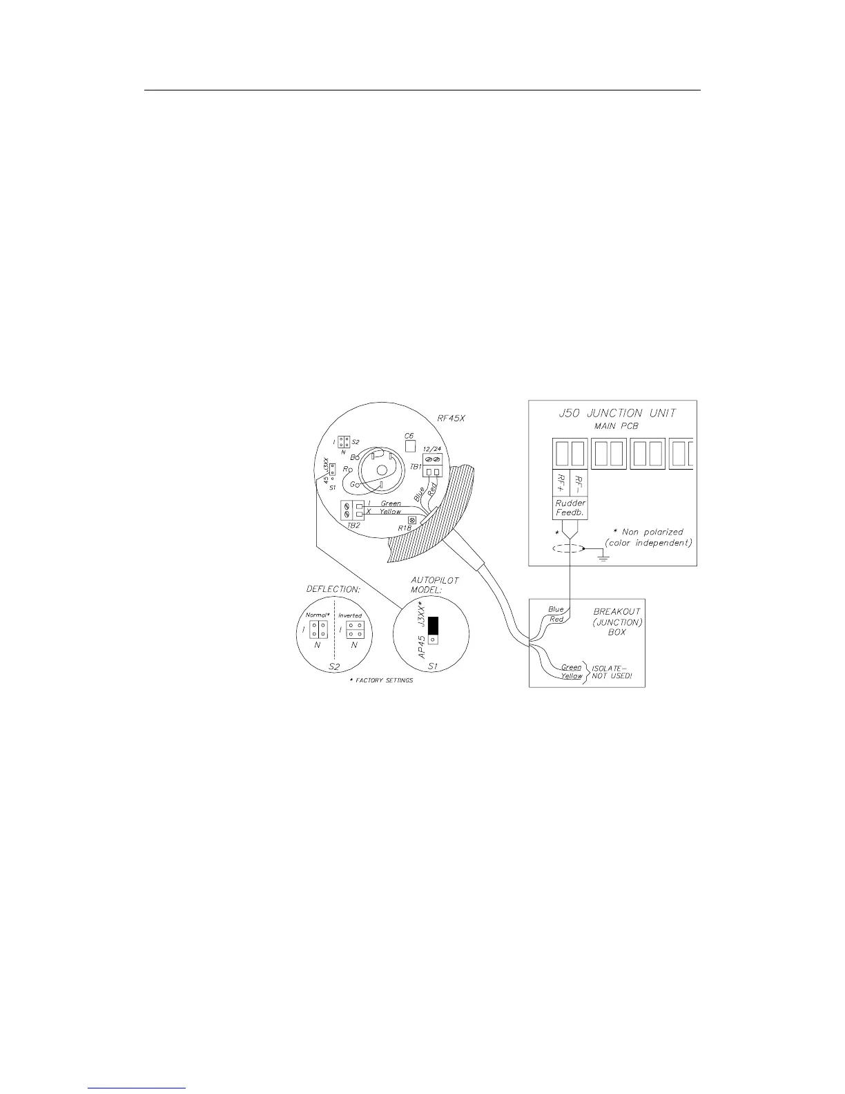
The cable should be connected to the junction unit according to
Figure 4-5. When splicing the cables in the breakout box, crimp
the enclosed pins on each wire of the extension cable to avoid
cutting off the wires at the terminal point when the screws are
tightened.
The screen must be connected in the junction unit.
Note ! The green and yellow wires are not used and must be isolated!
For final alignment, see page 79.
Figure 4-5 RF45X Rudder Feedback Unit Connection