Simrad AP50 Autopilot
78 20221032B
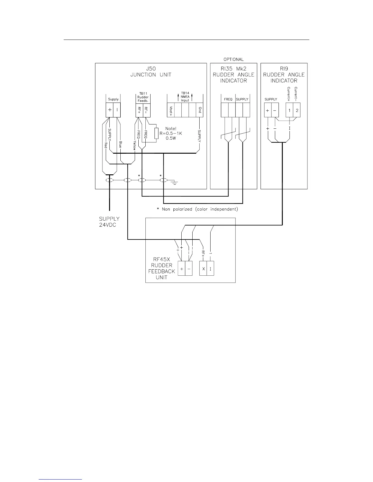
Figure 4-6 RF45X Connection to RI9 Rudder Angle
Indicators and RI35 Mk2 (optional)
The above connection diagram shows how to connect an RI9
Rudder Angle Indicator to a system with RF45X Rudder
Feedback Unit. For connection of RI35 Mk2 Rudder Angle
Indicators only, refer to the RI35 Mk2 manual.
This connection gives full functioning indicator(s) also with the
autopilot switched off. To have the indicator(s) switched off
with the autopilot, connect indicator(s) and rudder feedback
supply+ to J50 Vbat+ instead of J50 Supply+.
Note ! The resistor R (0.5-1K, 0.5W) has to be mounted. The resistor is
not supplied by Simrad.