Simrad AP50 Autopilot
80 20221032B
4.8 RF14XU Rudder Feedback Unit
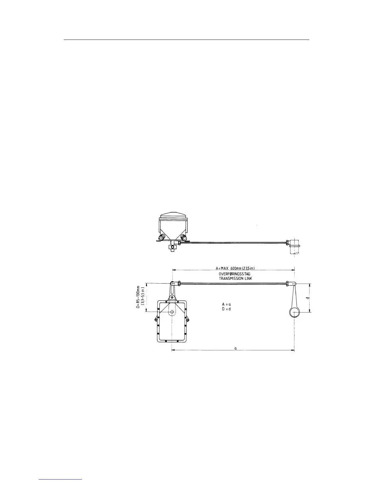
Mechanical mounting
Before installation check that the alignment mark on the
mounting plate agrees with the mark on the shaft. Bring the
rudder to Midships position. The feedback unit should be
mounted on a plane surface and secured by bolts through the
three holes in the mounting plate. It should be linked to the
rudder in accordance with Figure 4-7. It is important that the
linkage is linear, i.e. the A-a and D-d are pairs of equal length.
This will give a ratio 1:1 between the rudder angle and that of
the feedback unit shaft. Final adjustment is made by loosen the
fixing screws for the potentiometer, and carefully turn the
potentiometer for correct positioning.
Note ! If the RF14XU is mounted with the shaft pointing upwards, the
yellow and the blue lead to the potentiometer inside must be
interchanged (See Figure 4-9).
Figure 4-7 RF14XU - Mounting
Electrical installation
The cables are carried through cable glands. If required, to avoid
any mechanical damage, the cables should be run in a conduit
between the rudder feedback unit and the junction unit or rudder
angle indicator. Electrical connection is shown in the cabling
diagram. The cable screen must be connected to the internal
ground terminal. Ref. Figure 4-8.