Installation
20221032B 75
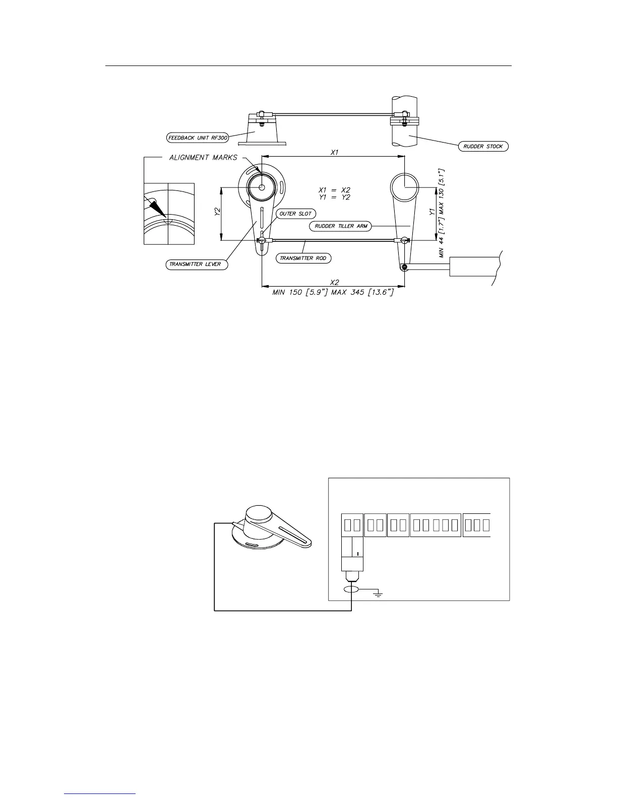
Figure 4-2 RF300S Rudder Feedback Unit Mounting
(019356)
Note ! Due to space limitations, it may be necessary to cut the length of
the transmitter rod to move the RF300S closer to the rudderpost.
Tighten the mounting screws for both the RF300S Rudder
Feedback Unit and the transmitter rod ball joint.
In order to verify that the mechanical linkage to the RF300S is
not obstructed, have someone observe the RF300S unit while
someone else turns the helm wheel through the complete range
of travel from full port to full starboard rudder. Connect the
RF300S to the J50 Junction Unit as shown in Figure 4-3
JUNCTION UNIT
MAIN PCB
Rudder
Feedb.
*
* NON POLARIZED
(COLOR INDEPENDENT)
RF +
RF
Figure 4-3 RF300S Rudder Feedback Unit Connection