Installation
20221032B 113
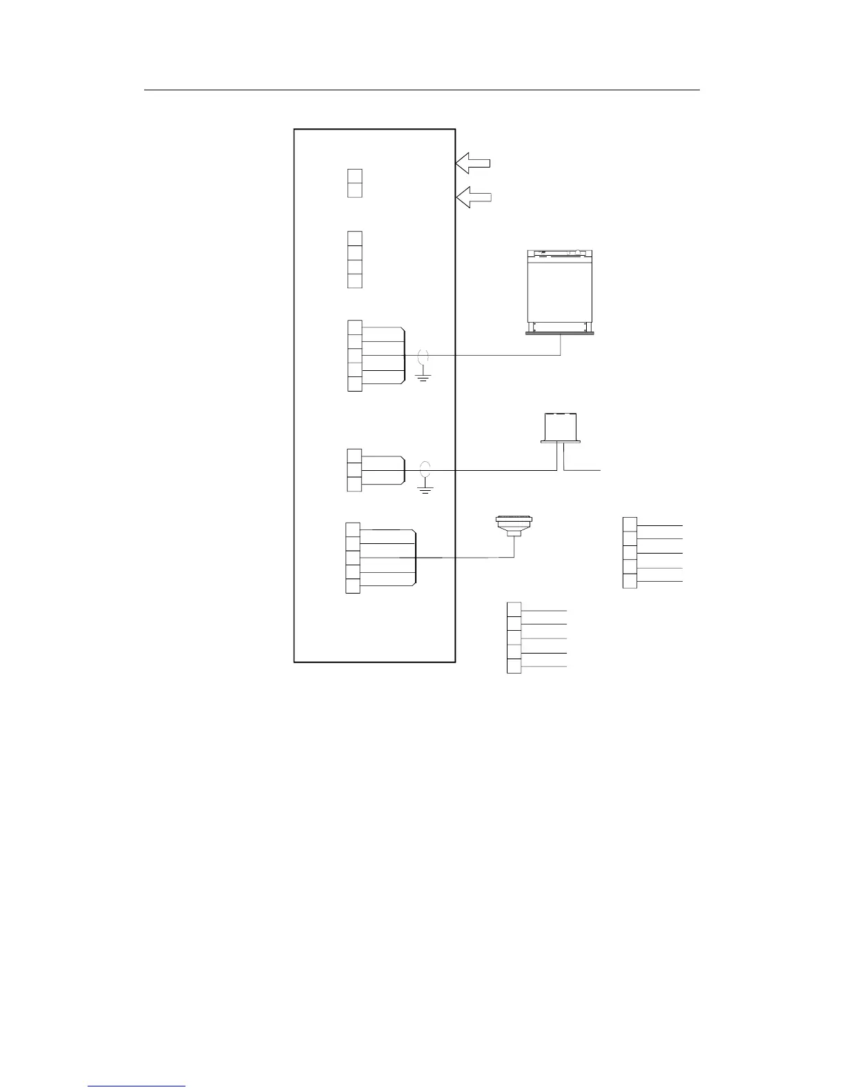
COM
STBD
PORT
ENAB
SIN
COS
GND
Vref
SIN
HI
LO
NFU
COS
MAGN. COMP
ANALOG
GYRO
MAGNETIC COMPASS
WITH CD100A COURSE
DETECTOR
FLUXGATE COMPASS
WITH SINE/COSINE
OUTPUT
DC SUPPLY
RGC10/RGC50
GYRO COMPASS
R1
R2
S1
S2
S3
CI300X COMPASS INTERFACE
ROBNET
CONNECTIONS
TB1
TB2
TB3
TB4
TB5
ALARM
OUTPUT
(Normally open)
1
4
5
3
2
CD100 CONNECTIONS:
NON FOLLOW UP
STEERING
LEVER
ALARM
WHITE
GREY
YELLOW
GREEN
BROWN
ALT. 1
MAGN. COMP
Vref
SIN
HI
LO
COS
To identify the black wires,
measure 8-12 ohm between
orange and black* and 6-10
ohm between green and
black**.
Third black wire not in use.
ORANGE
BLUE
BLACK**
GREEN
BLACK*
ALT. 2
MAGN. COMP
Vref
SIN
HI
LO
COS
Figure 4-42 CI300X Compass Interface Unit Connections
Note ! The CD100 is a previous model and its cable has a connector
that must be cut off for connection in the AP50 system (e.g. to
the CI300X or the CDI35).