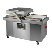
MODEL 600A
COVER ADJUSTMENT PROCEDURE
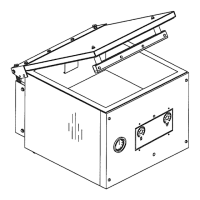
Reference Drawing:# 005C0324
# 004C0122
PROBLEM: MACHINE TABLE AND COVER SEEMS TO BE STRAIGHT, LID GASKET IS GOOD
BUT COVER DOES NOT SIT PROPERLY ON BOTH SIDES OF TABLE.
1. Floor should be flat (within 1/8" approx.).
2.2 Loosen the two bolts of the guide arm axis (See drawing #004C0122; items #23).
2.3 Now move the cover on each side and check how cover sits on the table. Distance
between table and lid gasket should be less than 1/16" approx. If so, go to step 3.0 for
guide arm adjustment. Otherwise go to step 2.4 for central arm adjustment.
2.5 When closing cover (guide arm axis still loose), if cover is not sitting properly on either the
front or rear of the table, you have to change the height of the flange bearings (See
drawing # 004C0122; item #12) until cover is seating properly on each side. Normally shaft
is centered in the table holes and the height is adjusted in a way that cover will slightly
touch the back side of the table first.
3. Adjustment of guide arm: Both length of the guide arm and position on the guide arm axis have to
be adjusted. Each of these should be adjusted separately. Fix the lower axis in a central position
(centered in the holes) then adjust guide arm length until cover sit correctly on the right side.
Move cover to the left side and check if cover sits correctly, if not move lower axis position and
change length of the guide arm. Move the cover back to its original position to confirm, normally
multiples tryout is required. Make sure there is no stress is transferred to the guide arm when
machine is operating, stress induced arm will cause premature component fail.