Do you have a question about the SIYI FT24 and is the answer not in the manual?
Explains symbols used in the manual for important information.
Provides essential safety guidelines for operating the FT24 radio system.
Details battery requirements and precautions for the FT24 transmitter.
Information on the proper use and handling of the SD card.
Guidance on storing, carrying, and recycling the SIYI radio system.
Highlights the key features and capabilities of the FT24 radio system.
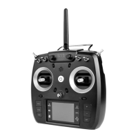
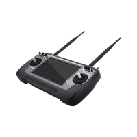
Identifies and describes the various physical parts of the FT24 transmitter.
Details the interface and tuner ports on the FT24 transmitter.
Describes the buttons and switches on the FT24 transmitter.
Explains the function and operation of the digital trim controls.
Lists the technical specifications for the FT24 transmitter and receiver.
Explains the meaning of different LED indicators on the FT24 transmitter.
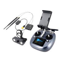
Lists the items included in the FT24 radio system package.
Guidance on correctly positioning the transmitter antenna for optimal signal.
Step-by-step instructions for binding the FT24 transmitter to receivers.
Explains the options for throttle joystick types and how to set them.
Details the supported battery types and power supply options for the transmitter.
Details the information displayed on the main menu screen, including model name, battery, and signal status.
Allows real-time monitoring and configuration of all 16 communication channels.
Enables selection, renaming, copying, and resetting of model data.
Instructions for saving and selecting up to 32 model configurations.
Guides on renaming saved model data using a virtual keyboard.
Provides steps for copying model data for backup and sharing.
Allows resetting selected groups of configuration data.
Allows selection and customization of various model types.
Instructions for selecting a model type and its implications.
Configures channel output values and limits for servos.
Enables free mapping of channels to joysticks, switches, buttons, and dials.
Allows reversing the output direction of a selected channel.
Sets the middle position of channel output and fine-tunes flight attitude.
Adjusts the stepping value for the Sub-Trim function.
Configures fail-safe settings to protect the model in case of signal loss.
Configures programming and mixing for complex model operations.
Enables experienced users to train new talents using two transmitters.
Instructions for linking transmitters using a trainer cable.
Instructions for linking transmitters wirelessly for trainer mode.
Sets a fixed output value for the throttle channel.
Forces the throttle channel to output a fixed value.
Supports up to 3 groups of curves for adjusting throttle and pitch.
Adjusts the response speed of servos.
Adjusts channel output value using a physical switch for better control.
Reduces throttle output for engine-powered models.
Supports up to 2 timers for flight monitoring.
Sets a minimum voltage limit to trigger voice alerts.
Allows simultaneous control of up to three drones.
Enables relay control between two transmitters for long-range flight.
Configure basic functions of the FT24 transmitter, including language and throttle type.
Adjust screen brightness and sleep time for the transmitter.
Configure output settings for external devices connected to the transmitter.
Calibrate the transmitter joysticks for accurate control.
Calibrate the transmitter knobs for accurate output.
Export and import transmitter settings and model data via SD card.
Guides users through the simplified ESC calibration process.
Allows users to customize voice prompts for switches and functions.
Setup different signal modes (S.BUS, PPM, PWM) for FR receivers.
Configure baud rate for datalink/telemetry function.
Displays the real-time working status of the RF transmission.
Manually calibrate receiver RX Voltage and PWR Voltage for telemetry.
Redefine PWM channel mappings for FR receivers.
Setup and manage the linked Bluetooth module for the transmitter.
Configure settings for external radio modules like FM30 and R9M.
Details PPM/S.BUS signal output for external modules.
Explains R9M AST mode for communication with R9M radio modules.
Steps for upgrading firmware using a USB connection and SIYI Assistant.
Instructions for upgrading firmware wirelessly over-the-air.
OTA upgrade procedure when receiver and transmitter are bonded.
OTA upgrade procedure when receiver and transmitter are not bonded.
Contact information and process for product repair inquiries.
Details SIYI's policies for return, refund, replacement, and warranty.
Conditions for requesting a return or refund within seven days of receipt.
Conditions for requesting a product replacement within fifteen days of receipt.
Information on obtaining warranty repair service within one year.
| Frequency | 2.4GHz |
|---|---|
| Receiving Sensitivity | -105dBm |
| Operating Voltage | 7.4V |
| Output Signal | PPM/SBUS |
| Modulation | FHSS |
| Frequency Range | 2.400GHz-2.483GHz |
| Battery Type | Li-ion |
| Battery Capacity | 2500mAh |
| Transmitting Power | 100mW (20dBm) |
| Max Output Power | 20dBm |