COSMOS DRIVER SERIES 3000 - USE AND MAINTENANCE MANUAL
logic level of the two input signals ENABLE IN and RESET IN.
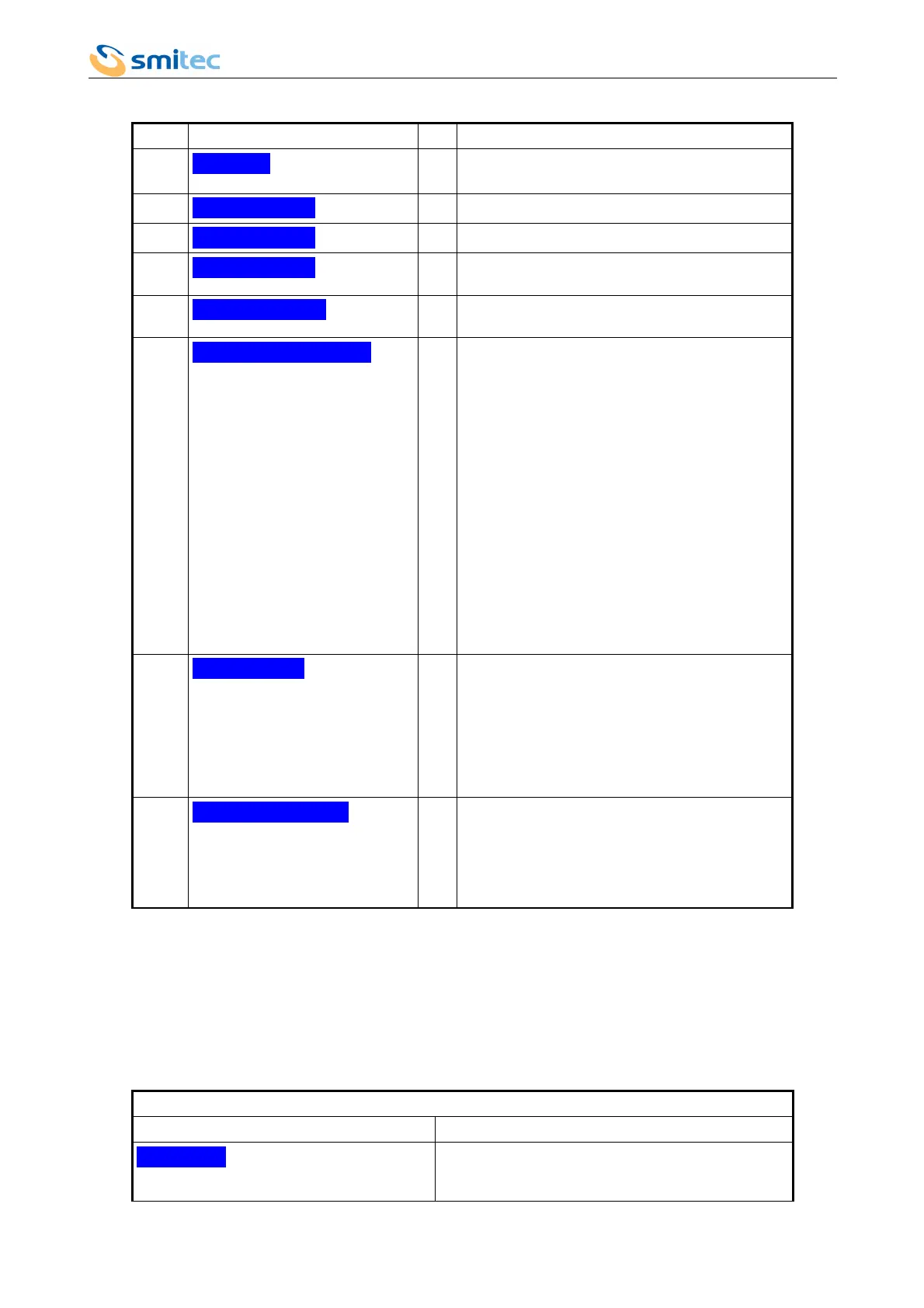
Menu Entry Lev. Description
1.6
>ANALOG
- It includes the setting concerning the analogue
controller.
1.6.1
DRIVE STATE
- It displays the analogue controller status.
1.6.2
RESET ERROR
1 It allows cancelling the error condition.
1.6.3
RESET LEVEL
3 L = The reset signal is active and low.
H = The reset signal is active and high.
1.6.4
ENABLE LEVEL
3 L = The enabling signal is active and low.
H = The enabling signal is active and high.
1.6.5
K-VIN/VEL[V/rpm]
2 Speed constant of the analog input, expressed in
rpm per input Volt.
It allows modifying the gain, to transform the speed
analogue reference in rpm, according to the
following formula:
where,
Vel
= speed in rpm required to the motor;
Kv
= speed constant;
Vin
= voltage analogue reference (from -10V to
+10V);
Voff
= analogue input offset (from -5V to +5V).
It is recommended to use the whole dynamic range
of the input, so as to increase the signal/noise ratio.
Min=0, Max=+350.
1.6.6
OFFSET [V]
2 Offset voltage of the analogue input, expressed in
Volt.
This voltage is added algebraically to the voltage
representing the speed analogue reference sent to
the driver. In any case, this sum can not exceed the
limits of the analogue input (± 10V). For further
information, please refer to
Kv
data.
Min=-5.000, Max=+5.000.
1.6.7
READY TIME [s]
Delay for the activation of the READY-OUT signal,
when the driver is ready to be enabled.
It allows postponing the request of enabling,
starting from the moment when the driver is no
longer in error status.
Min=0, Max=+20.
7.2.9.3 Analogue controller status
The VISIO displays some “Messages” about the analogue interface status.
Please remember that the priority of the messages about the analogue interface is lower than the “driver errors”. In case
of simultaneous messages of driver error and analogue interface, the driver error will be signalled first.
A message concerning the analogue interface does not require to carry out the procedure to cancel it; it will be
automatically cancelled when the required conditions are fulfilled. By contrast, the driver error must be cancelled by
means of the option RESET ERROR on the LCD. If the error persists, the operation will have no effect.
WARNING codes
Warning text Explanation
WARN 50
At the driver start, if the auxiliary voltage is available,
you must wait for the minimum mains voltage before
proceeding.
Ver. 1.07 Pag. 74