l AC and DC conduit entries:ConnectionpointsoftheSafetySwitch.
l AC and DC conduit entries:ConnectionpointsoftheStorEdgeConnectionUnit.
l ON/OFF switch:TurningthisswitchONstartstheoperationofthepoweroptimizers,enablespower
productionandallowstheinvertertobeginexportingpowertotheutilitygrid/backed-uploads.
TurningitOFFreducesthepoweroptimizervoltagetoalowsafetyvoltageandinhibitsexportationof
power.WhenthisswitchisOFF,theinvertercontrolcircuitryremainspoweredup.
l LCD light button:PressingthisbuttonlightsuptheLCDfor30seconds.Inaddition,youcanpress
thisbuttontoviewinverterstatusscreensandaccessconfigurationmenuoptions,asdescribed
ConfiguringtheInverterUsingtheLCDLightButtononpage55.
l Two communication glands,forconnectionofinvertercommunicationoptions.Eachglandhas
threeopenings.RefertoSettingUpCommunicationtotheMonitoringPlatformonpage69formore
information.
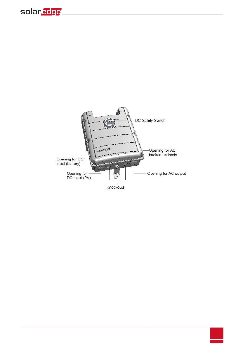
StorEdge Connection Unit
Figure 9: StorEdge Connection Unit
TheStorEdgeConnectionUnitincludes:
l DC safety switch:disconnectsboththepositiveandnegativeconductorsofthePVandthepositive
andnegativeconductorsofthebattery.
l Openings for conduit entry:Fouropeningsarereadytouseandhavesealingcovers.Twoopenings
areclosedwithknockouts.Ifrequired,opentheknockoutsasdescribedinOpeningConduitKnockouts
onpage96.
Chapter 3: Installing the Inverter
SolarEdge-StorEdge Installation Guide MAN-01-00262-1.2
23