38
HCD-CL5MD
9. Press the ENTER/YES button display “EFB = MO-P”.
Then, the optical pick-up moves to the pit area automatically
and servo is imposed.
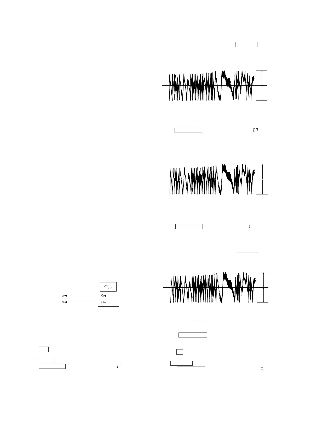
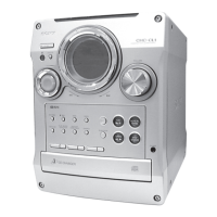
10. Observe the waveform of the oscilloscope, and check that the
specified value is satisfied. Do not move ./> .
(Traverse Waveform)
Checking Procedure:
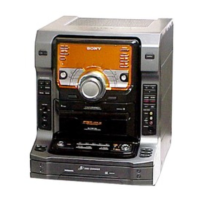
1. Connect an oscilloscope to CN105 pin 4 (TE) and CN105 pin
6 (VC) of the BD (MD) board.
2. Load a test disc (MDW-74/GA-1). (Refer to Note 1.)
3. Press the M button, and move the optical pick-up outside the
pit.
4. Move ./> and display “EF MO CHECK”(C14).
5. Press the ENTER/YES button and display “EFB =
MO-R”.
(Laser power READ power/Focus servo ON/tracking servo OFF/
spindle (S) servo ON)
V : 0.5 V/div
H : 10 ms/div
Input : DC mod
Oscilloscope
BD (MD) board
CN105 pin 4 (TE)
CN105 pin 6 (VC)
VC
A
B
Specified value : Below 10% offset value
Offset value (%) = X 100
IA – BI
2 (A + B)
VC
A
B
Specified value : Below 10% offset value
Offset value (%) = X 100
IA – BI
2 (A + B)
6-6-4. Auto Check
This test mode performs CREC and CPLAY automatically for
mainly checking the characteristics of the optical pick-up. To
perform this test mode, the laser power must first be checked.
Perform Auto Check after the laser power check and Iop compare.
Procedure
1. Press the ENTER/YES button. If “LDPWR” is displayed, it
means that the laser power check has not been performed. In
this case, perform the laser power check and Iop compare, and
then repeat from step 1.
2. If a disc is in the mechanical deck, it will be ejected forcibly.
“DISC IN” will be displayed in this case. Load a test disc (MDW-
74/GA-1) which can be recorded.
3. If a disk is loaded at step 2, the check will start automatically.
4. When “XX CHECK” is displayed, the item corresponding to
XX will be performed.
When “06 CHECK” completes, the disc loaded at step 2 will be
ejected. “DISC IN” will be displayed. Load the check disc (MD)
TDYS-1.
5. When the disc is loaded, the check will automatically be resumed
from “07 CHECK”.
6. After completing to test item 12, check OK or NG will be
displayed. If all items are OK, “CHECK ALL OK” will be
displayed. If any item is NG, it will be displayed as “NG:xxxx”.
When “CHECK ALL OK” is displayed, it means that the optical
pick-up is normal. Check the operations of the other spindle motor,
sled motor, etc.
When displayed as “NG:xxxx”, it means that the optical pick-up is
faulty. In this case, replace the optical pick-up.
6-6-5. Other Checks
All the following checks are performed by the Auto Check mode.
They therefore need not be performed in normal operation.
6-6-6. Traverse Check
6-6-7. Focus Bias Check
6-6-8. C PLAY Check
6-6-9. Self-Recording/Playback Check
6-6-6. Traverse Check
Connection :
VC
A
B
Specified value : Below 10% offset value
Offset value (%) = X 100
IA – BI
2 (A + B)
7. Press the ENTER/YES button and display “EFB = MO-W”.
8. Observe the waveform of the oscilloscope, and check that the
specified value is satisfied.
(Write power traverse checking)
(Traverse Waveform)
6. Observe the waveform of the oscilloscope, and check that the
specified value is satisfied. Do not move ./> .
(Read power traverse checking)
(Traverse Waveform)
11. Press the ENTER/YES button display “EF MO CHECK”
(C14).
The disc stops rotating automatically.
12. Press the Z button and remove the disc.
13. Load the check disc (MD) TDYS-1.
14. Move ./> and display “EF CD CHECK” (C15).
15. Press the ENTER/YES button and display “EFB =
CD”.
Servo is imposed automatically.