35
HCD-FL5D
Mode: Playback
1. Insert the WS-48B into the deck B.
2. Press the hH button on the deck B.
3. Press the [CD SYNC HI-DUB] button in playback mode.
Then at HIGH speed mode.
4. Adjust RV1001 on the SW board so that frequency counter reads
6,000 ± 180 Hz.
5. Press the [CD SYNC HI-DUB] button.
Then back to NORMAL speed mode.
6. Adjust RV1002 on the SW board so that frequency counter reads
3,000 ± 90 Hz.
Adjustment Location: SW board
Sample Value of Wow and Flutter: 0.3% or less W. RMS (JIS)
(WS-48B)
REC BIAS ADJUSTMENT DECK B
Procedure:
In the MC test mode, the “REC memory mode” is convenient for
this adjustment. In the “REC memory mode” , when the REC starts
the input signal FUNCTION is switched to VIDEO automatically.
When the REC stops, the tape returns near to the recording start
position.
1. Press [MD $VIDEO%] button to select VIDEO. (This step is not
necessary if the above test mode has already been set)
2. Insert a tape into deck B.
3. After press [REC PAUSE/START] button, press [REC
PAUSE/START] button, then rec ording start.
4. Mode: Record
5. Mode: Playback
6. Confirm the playback signal recorded in step 3 becomes
adjustable level as follows.
If these levels are not adjustable level, adjust the RV2 (L-CH)
and RV52 (R-CH) on the SP RELAY board to repeat steps 4
and 5.
Adjustable level: Playback output of 315 Hz to playback output
of 10 kHz: ±1.0 dB
Adjustment Location: SP RELAY board
3. Mode: Playback
4. After the adjustments, apply suitable locking compound to the
pats adjusted.
Adjustment Location: Playback Head (Deck A).
Record/Playback/Erase Head (Deck B).
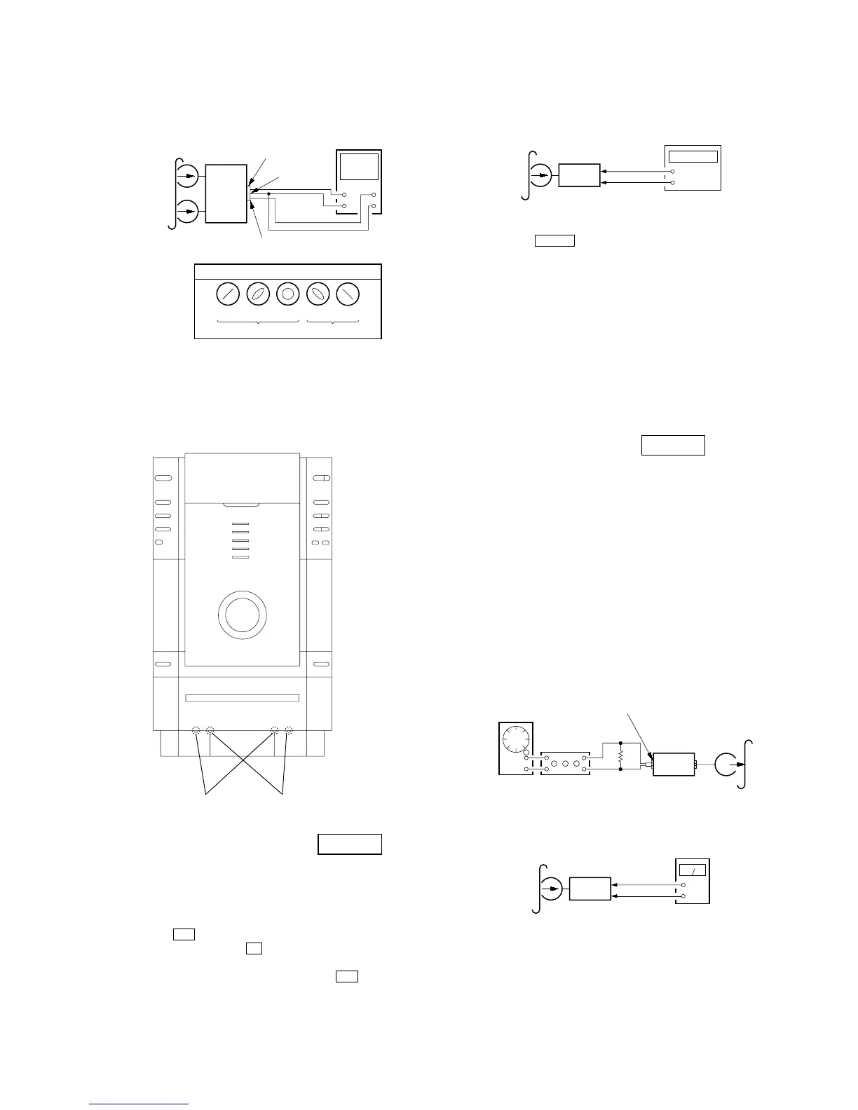
TAPE SPEED ADJUSTMENT DECK B
Note: Start the Tape Speed adjustment as below after setting to the test
mode.
In the test mode, the tape speed is high during pressing the
[CD SYNC HI-DUB] button.
Procedure:
1. Press ?/1 button to turn the set ON.
2. Press three buttons x , [DISPLAY] and [CD SYNC HI-DUB]
simultaneously.
To release from the test mode, press the ?/1 button.
SP
REALY
baord
CN804
set
test tape
P-4-A100
(10 kHz, –10 dB)
pin
5
oscilloscop