36
HCD-FL5D
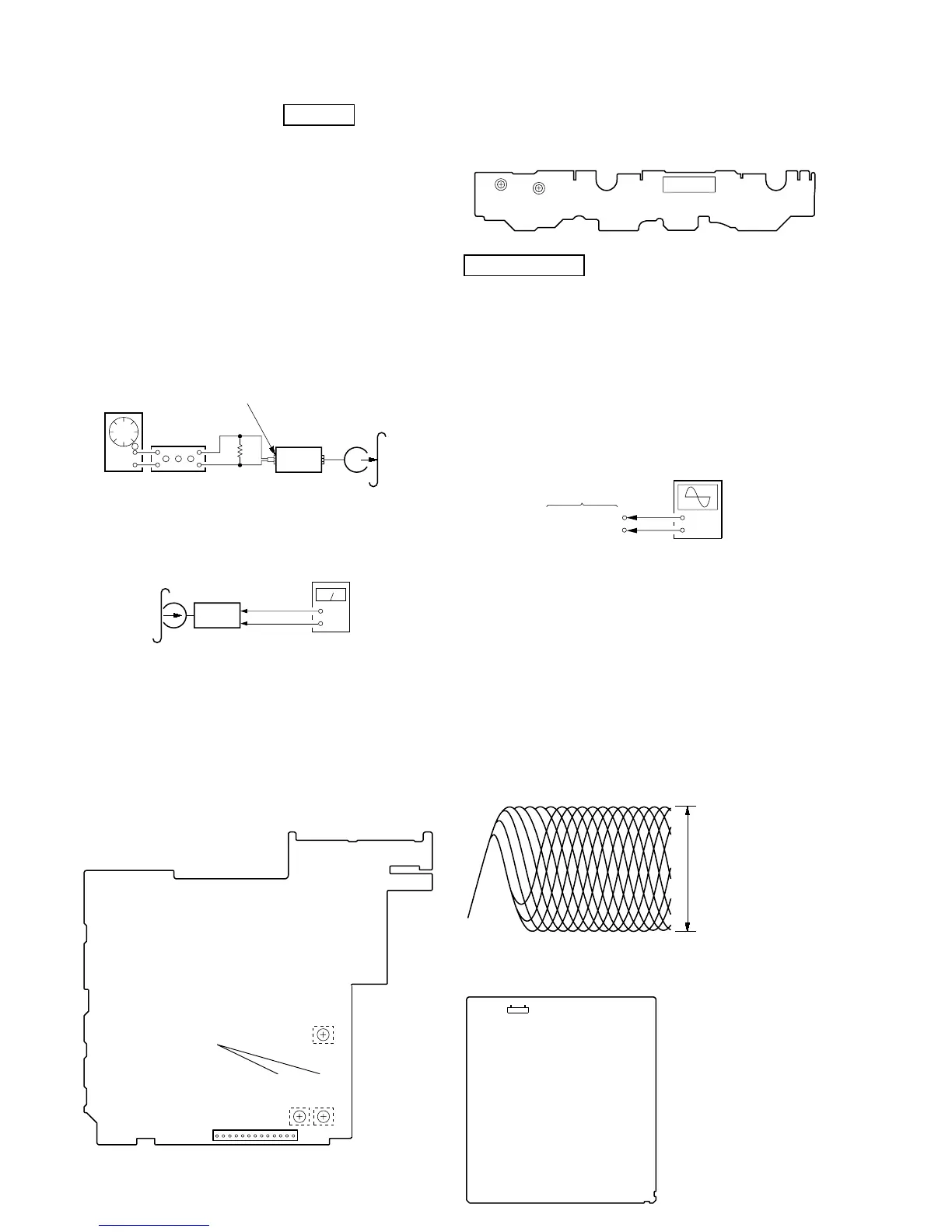
REC LEVEL ADJUSTMENT DECK B
Procedure:
In the MC test mode, the “REC memory mode” is convenient for
this adjustment. In the “REC memory mode” , when the REC starts
the input signal FUNCTION is switched to VIDEO automatically.
When the REC stops, the tape returns near to the recording start
position.
1. Press [MD $VIDEO%] button to select VIDEO. (This step is not
necessary if the above test mode has already been set)
2. Insert a tape into deck B.
3. After press [REC PAUSE/START] button, press [REC PAUSE/
START] button, then recording start.
4. Mode: Record
5. Mode: Playback
6. Confirm the play back signal recorded in step 3 becomes
adjustable level as follows.
If these levels are not adjustable level, adjust the RV53 (R-CH)
on the SP RELAY board to repeat steps 4 and 5.
Adjustable level:
CN804 PB level: 47.2 to 53.0 mV (–24.3 to –23.3 dB)
Adjustment Location: SP RELAY board
set
DSP board
MD (VIDEO) (J701)
315 Hz, 50 mV (–23.8 dB)
blank tape
CS-123
600
Ω
attenuator
AF OSC
+
–
set
recorded
portion
SP RELAY board
CN804 Pin
3
(GND)
SP RELAY board
CN804
Pin
5
(R-CH)
level meter
TAPE SPEED
ADJUSTMENT
RV1002
RV1001
(NORMAL) (HIGH)
CN1001
– SW BOARD (Component Side) –
CN804
13
1
– SP RELAY BOARD (Conductor Side) –
REC BIAS
ADJUSTMENT
REC LEVEL
ADJUSTMENT
(L-CH)
(R-CH)
RV52
RV2
RV53
AUTO SERVO ADJUSTMENT
After parts related to the servo circuit (RF amplifier (IC001), DSP
(IC509), motor driver (IC501), EEPROM (IC903) so on) are
replaced, re-adjusting the servo circuit is necessary. Select “ALL”
at “1. DRIVE AUTO ADJUSTMENT” (Refer to page 28 in TEST
MODE) and adjust DVD-SL (single layer), CD and DVD-DL (dual
layer).
Ver 1.5
DVD SECTION
RF LEVEL CHECK
Connection:
Procedure:
1. Connect an oscilloscope to test point 1 pin and 3 pin of
CN901 on the MB board.
2. Turn the power on.
3. Put the disc (LUV-P01) (Part No.: 4-999-032-01) (CD) in to
playback.
4. Confirm that oscilloscope waveform is clear and check RF
signal level is correct or not.
5. Put the disc (TDV-520CSO) (Part No.: J-2501-236-A) (DVD)
in to playback.
6. Perform confirmation in the same manner as step 4.
Note: A clear RF signal waveform means that the shape “◊” can be clearly
distinguished at the center of the waveform.
Checking Location:
oscilloscope
MB board
CN901
3
pin
CN901
1
pin
+
–
RF signal waveform
VOLT/DIV: 200 mV
TIME/DIV: 500 ns
CD: 1.05
±
0.2 Vp-p
DVD: 1.09
±
0.2 Vp-p
– MB Board (Component Side) –
CN901
17