6
HCD-FL5D
NOTES ON HANDLING THE OPTICAL PICK-UP
BLOCK OR BASE UNIT
The laser diode in the optical pick-up block may suffer electro-
static break-down because of the potential difference generated
by the charged electrostatic load, etc. on clothing and the human
body.
During repair, pay attention to electrostatic break-down and also
use the procedure in the printed matter which is included in the
repair parts.
The flexible board is easily damaged and should be handled with
care.
NOTES ON LASER DIODE EMISSION CHECK
The laser beam on this model is concentrated so as to be focused
on the disc reflective surface by the objective lens in the optical
pick-up block. Therefore, when checking the laser diode emis-
sion, observe from more than 30 cm away from the objective lens.
LASER DIODE AND FOCUS SEARCH OPERATION
CHECK
Carry out the “S curve check” in “CD section adjustment” and
check that the S curve waveforms is output three times.
SERVICE POSITION
In checking the DSP/MB/MC/VIDEO boards, prepare jig.
SECTION 1
SERVICING NOTES
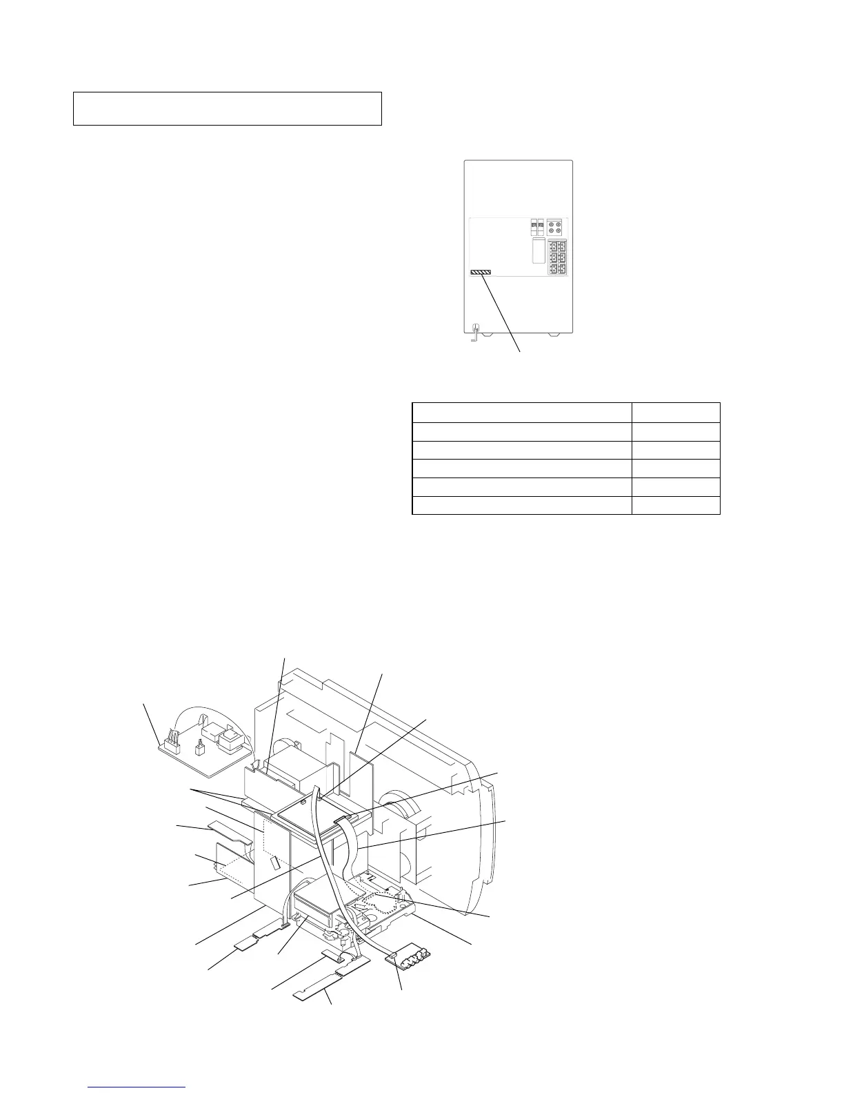
• MODEL IDENTIFICATION
– Back Panel –
MODEL PART No.
Singapore model 4-240-281-0
[]
Saudi Arabia model 4-240-281-1
[]
Australian model 4-240-281-2
[]
Mexican model 4-240-281-3
[]
Thailand model 4-240-281-4
[]
PART No.
extension cable (J-2501-217-A)
to the MB board (CN501)
and RF board (CN002)
extension cable (J-2501-198-A)
to the MB board (CN204)
and video board (CN701)
video board (CN701)
GC board
regulator board
SP relay board
DSP board
front rear AMP board
blue LED board
panel (L) board
panel (R) board
RF board (CN002)
mechanism deck
MB board (CN204)
SUB trans board
trans board
center SW AMP board
MB board (CN501)
Any board to put
MC board