INSTRUCTION, USE AND
MAINTENANCE MANUAL
GB
Page 13 of 58
1296-M010-0_P
Space s.r.l.
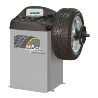
ER232R - ER234R - ER236R - ER238R - ER238RFM - ER248R - ERP248R
• Execute 4 holes (5 holes for ERP248R models) with
10 mm diameter on the floor by the holes on the
bottom floor;
• insert the small blocks (excluded from supply) into
the holes;
• fix the machine to the ground with 4 M8x80 mm
screws (5 screws for ERP248R models) (excluded
from supply) (Fig. 5 ref. 1) (or with 4 8x80 mm stud
bolts (5 screws for ERP248R models) (excluded from
supply)). Tighten the screws with an approximate
tightening torque of 70 Nm.
9.2 Fixtures contained in the packing
The packing case contains also the fixtures box.
Check that all the parts listed below are there (see
Fig. 6).
For ER232R - ER236R models
Code Description N.
GAR102
Ring nut with handwheel +
pusher ring
1
GAR111 Cones + protection cup 1
129571492 External data gauge 1
1300A004 Weight pliers 1
999072 Carriages counterweight 1
For ER234R - ER238R - ER238RFM - ER248R
models
Code Description N.
GAR101 Rapid ring nut + pusher ring 1
GAR111 Cones + protection cup 1
129571492 External data gauge 1
1300A004 Weight pliers 1
999072 Carriages counterweight 1
For ERP248R
Code Description N.
GAR108 Lock bush + pusher ring 1
GAR111 Cones + protection cup 1
129571492 External data gauge 1
1300A004 Weight pliers 1
999072 Carriages counterweight 1
9.0 MACHINE ASSEMBLY
After having freed the various components from the
packing check that they are complete, and that there
are no anomalies, then comply with the following in-
structions for the assembly of the components making
use of the attached series of illustrations.
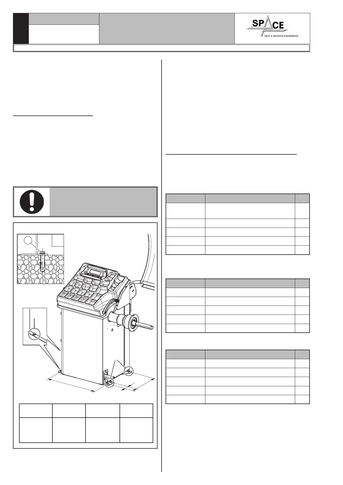
9.1 Anchoring system
The packed machine is fixed to the support pallet
through the holes prearranged on the frame. Such
holes can be used also to fix the machine to the ground,
through floor anchor small blocks (excluded from sup-
ply). Before carrying out the definitive fixing, check that
all the anchor points are laid down flat and correctly
in contact with the fixing surface itself. If not so, insert
shimming profiles between the machine and the fixing
lower surface, as indicated in Fig. 5.
IN CASE OF WHEEL WEIGHING
MORE THAN 30 KG, IT IS COM-
PULSORY TO FIX TO THE GROUND
BY MEANS OF SCREW ANCHORS.
X
b
a
1
X
X
c
Fig. 5
ER232R
ER234R
ER236R
ER238R
ER238RFM
ER248R
ERP248R
a= 270 mm a= 270 mm a= 270 mm a= 386 mm
b= 646 mm b= 646 mm b= 480 mm b= 580 mm
c= 54 mm