GB
Page 58 of 58
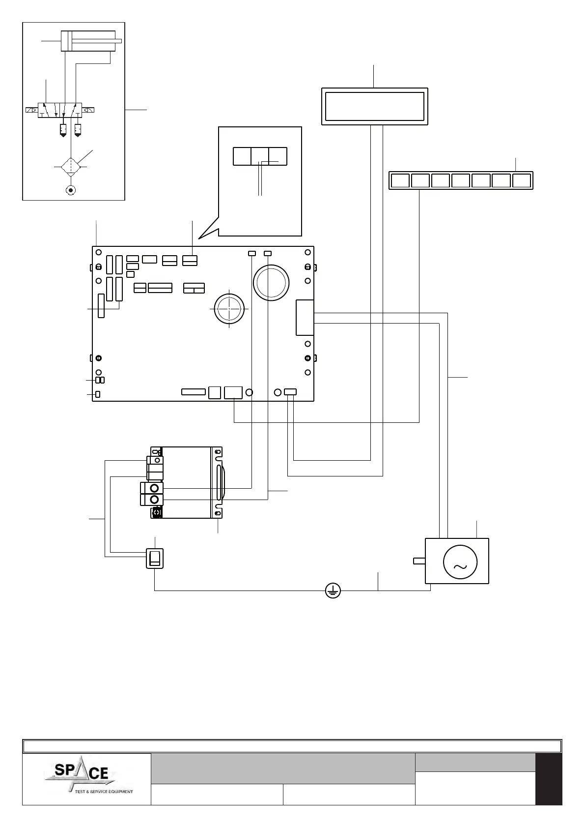
ELECTRICAL AND PNEUMATIC
CONNECTION DIAGRAM
Table N°A - Rev. 0
15
PIEZO
REAR
PIEZO
FRONT
DISC
ENCODER
GUARD
POWER SUPPLY SWITCH
WITH PLUG
1
2
3
4
5
6
7
GND
JP17
JP25
JP31
JP6
JP17B
JP17A
JP27
JP7
JP28
JP1
JP3
JP8
JP4
JP5
USB
JP16
JP15A
JP15
JP23
JP22
JP21
JP18
JP19
-
+
JP11
+
-
JP12
8
10
11
12
13
14
+24
14
LCD
9
M
16
17
18
1296-M010-0_P
Space s.r.l.
ER232R - ER234R - ER236R - ER238R - ER238RFM - ER248R - ERP248R
KEY
1 – LCD Display
2 – CPU Card
3 – Transformer
4 – Power supply switch with plug
5 – Motor
6 – Keyboard
7 – Ground cable
8 – Connection cable from switch to trans-
former
9 – Card power supply cables
10 – Motor cables
11 – Front piezo
12 – Rear piezo
13 – Encoder disc
14 – Carter micro
15 – Pneumatic tightening diagram
(only for ERP248R)
16 – Tightening drive cylinder
17 – 5/2 NC solenoid valves
18 – Separating filter