GB
Page 36 of 58
INSTRUCTION, USE AND
MAINTENANCE MANUAL
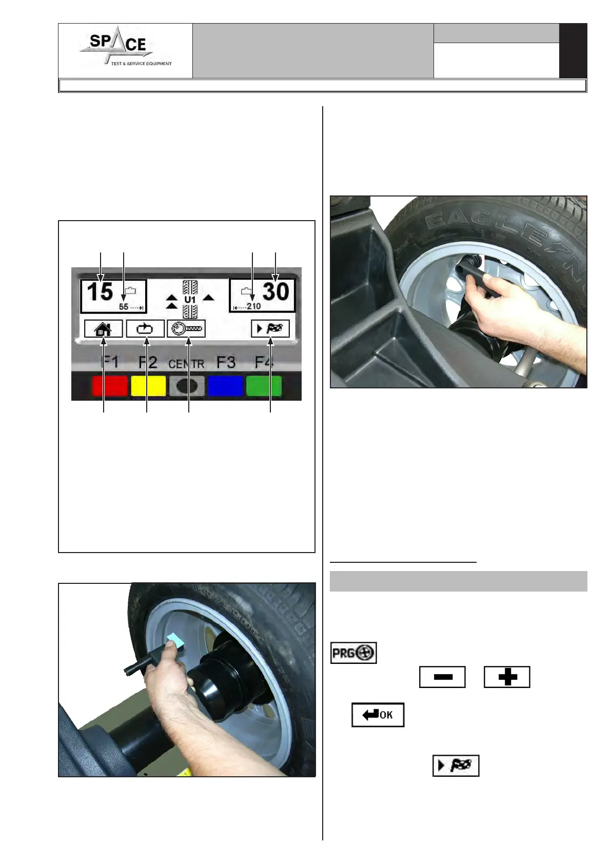
The display unit indicates the direction in which to
move the wheel to fit the weights and how much weight
and distance are needed to correct the unbalance
(Fig. 55).
Once the unbalance value of the inner and outer wheel
side is known, the wheel can be positioned properly.
Turn the wheel in the direction indicated by the arrows
(on the outer side, approximately at 12 o'clock) until
the correct position is reached (par. 15.3.2).
KEY
1 – Return to initial program phase (RED) (F1)
2 – Display next row of keys (YELLOW) (F2)
3 – Displays exact unbalance (pitch 1 g instead of
5 g) (CENTRAL)
4 – Distance for correcting the wheel inside unbal-
ance
5 – Performs spin (GREEN) (F4)
6 – Amount of weight to be fitted to inside of wheel
Fig. 55
1 2 3 5
6
7 4 6
Fit the adhesive weight in the manual distance caliper
as shown in Fig. 56.
Fig. 56
Read the outer distance measurement on the manual
distance caliper. Fit the adhesive weight on the outside
of the wheel (Fig. 57) at the indicated distance (in
the example at 210 mm) using a known weight (the
example 30 g). The position of the outer weight is not
visible but hidden inside. Turn the wheel until the cor-
rect point is reached (par. 15.3.2).
Fig. 57
Read the inner distance measurement on the manual
distance caliper. Fit the adhesive weight on the inside
of the wheel (Fig. 57) at the indicated distance (in the
example at 55 mm) using a known weight (the example
15 g). Turn the wheel until the correct point is reached
(par. 15.3.2). Check wheel balancing conditions by
making a trial spin. The display screen will show an
unbalance reset.
If the adhesive weight has to be hidden behind spokes,
refer to “weights hidden behind spokes mode” in
Chapt. 18.
The ALU-S procedure is completed.
15.4.13 ALU 1 procedure
Valid for car
Make sure there are no stones and/or mud on the
wheel. Remove any counterweights. Fit the wheel and
make sure it is properly fastened (Chap. 12). From
the first display page (Chap. 14) press the “F3 key”
to select the type of desired correction;
Through the keys or display the
ALU 1 function. Confirm the selection with the “CEN-
TR”
key. Determine the wheel dimensions
using the specific manual distance caliper (par. 15.1).
After entering the data, close the protection guard, if
fitted, or press “F4” to perform the wheel
spin; in just a few seconds, the wheel runs at normal
speed and the wheel balancer display shows wheel
rotation (Fig. 58). Do not touch the wheel while taking
measurements. At the end of the spin the wheel will
1296-M010-0_P
Space s.r.l.
ER232R - ER234R - ER236R - ER238R - ER238RFM - ER248R - ERP248R