INSTRUCTION, USE AND
MAINTENANCE MANUAL
GB
Page 37 of 58
stop automatically, also taking into account the meas-
ured unbalance so the external weight fitting point is
exactly at 12 o’ clock.
Fig. 58
Press in case of emergency
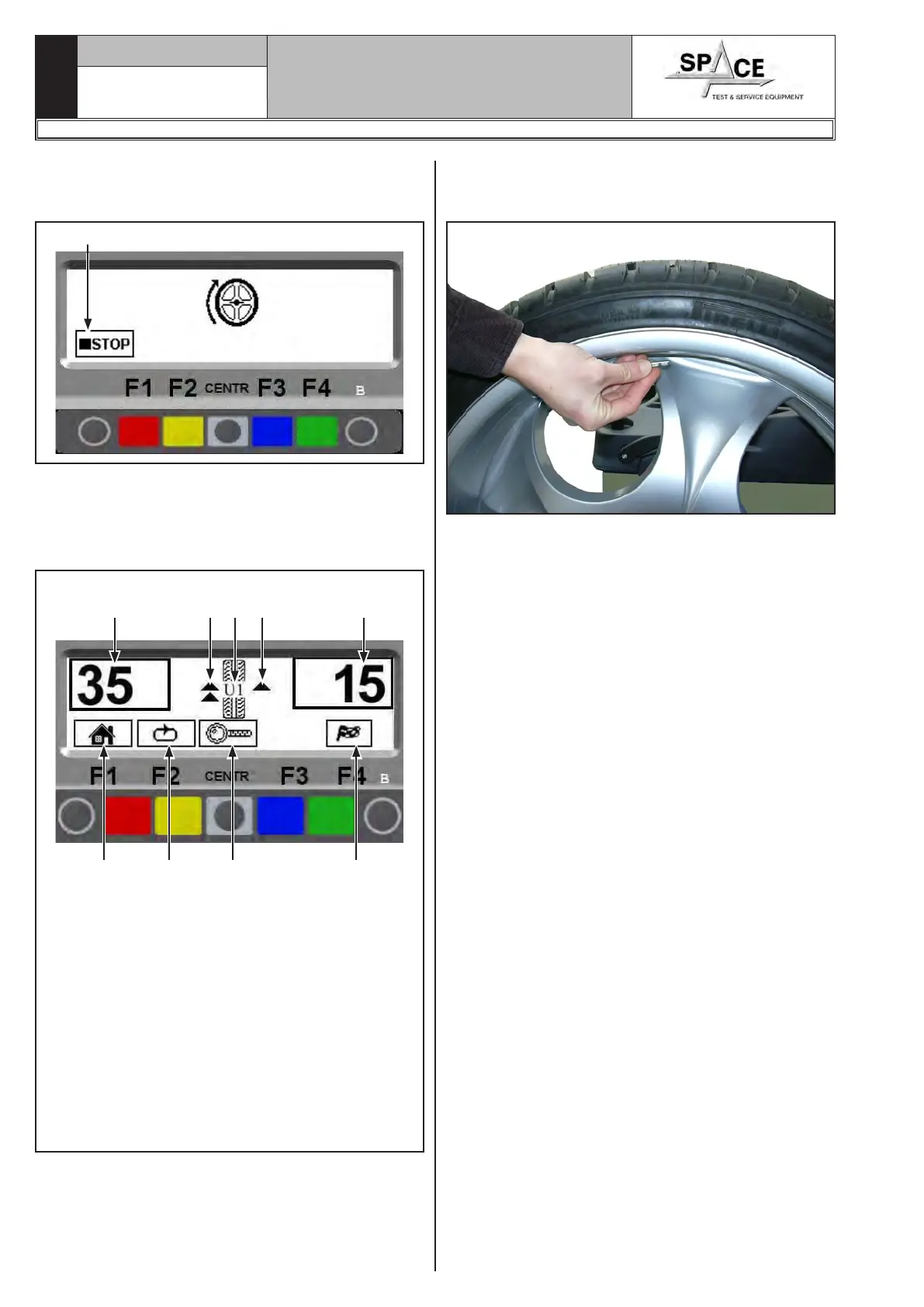
The display screen shows the weight required to cor-
rect the unbalance (Fig. 59).
Turn the wheel at the point indicated by the arrows,
until the correct position has been reached to correct
the unbalance (par. 15.3.2).
KEY
1 – Return to initial program phase (RED) (F1)
2 – Display next row of keys (MATCHING PROCE-
DURE) (YELLOW) (F2)
3 – Displays exact unbalance (pitch 1 g instead of
5 g) (CENTRAL)
4 – Total outer weight
5 – Performs spin (GREEN) (F4)
6 – Total inner weight
7 – Arrows to help positioning manually the wheel
(see Par. 15.3.2) in correction weight fitting
point
8 – N° of current user
Fig. 59
1 2 3 5
6
4
87 7
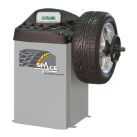
Fit the adhesive weight on wheel outer side. The outer
side weight must be positioned by hand on the verti-
cal (Fig. 60).
Fig. 60
To fit the adhesive weight on the inner part of the
wheel, turn the wheel in the direction of the arrows
until the correct position is reached (the arrow must
be horizontal).
The adhesive weight on the inner side of the wheel.
The outer side weight must be positioned by hand
high up on the vertical at 12 o'clock (Fig. 60), us-
ing a weight of pre-determined value (the example in
Fig. 59 shows 35 g).
Check the wheel balancing conditions and make a
trial spin.
The ALU 1 procedure is completed.
1296-M010-0_P
Space s.r.l.
ER232R - ER234R - ER236R - ER238R - ER238RFM - ER248R - ERP248R