GB
Page 32 of 58
INSTRUCTION, USE AND
MAINTENANCE MANUAL
15.3.3 Static balancing (STAT)
Make sure there are no stones and/or mud on the
wheel.
Remove any counterweights.
Fit the wheel and make sure it is fastened properly.
Press the “F3 key” from the initial program
page (see Chap. 14).
Enter the wheel measurements (Par. 15.1), close the
protection guard, if on issue or press “F4”
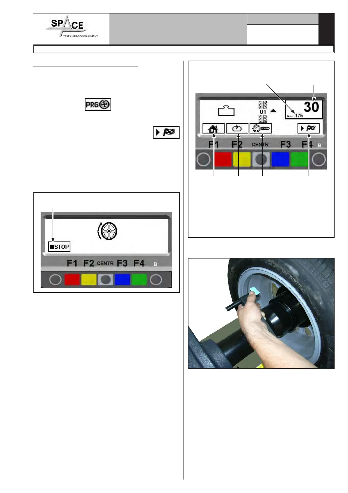
to perform the wheel spin; in just a few seconds, the
wheel runs at normal speed and the wheel balancer
display shows wheel rotation (Fig. 50). Do not touch
the wheel while taking measurements. At the end of
the spin, the wheel will stop automatically, taking into
account the measured unbalance so the outer weight
fitting position is at approx. 12 'o' clock.
Fig. 50Press in case of emer-
gency
The display unit indicates the direction in which to
move the wheel to fit the weight and how much weight
is needed to correct the unbalance.
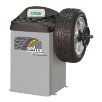
The display screen shows the distance for correcting
unbalance on small numbers. and the total weight to
be fitted (Fig. 51) on big numbers. Once the unbal-
ance value of the wheel side is known, the wheel can
be positioned properly.
Fig. 51
Total weight to be
fitted.
Distance for correcting
the unbalance.
KEY
1 – Return to initial program phase (RED) (F1)
2 – Display next row of keys
3 – Displays exact unbalance (pitch 1 g instead of
5 g) (CENTRAL)
4 – Performs spin (GREEN) (F4)
1 2 3 4
Fit the adhesive weight in the manual distance caliper
as shown in Fig. 52.
Fig. 52
Read the distance measurement on the manual dis-
tance caliper. Fit the adhesive weight on the outside
of the wheel (Fig. 53) at the indicated distance (in
the example at 175 mm) using a known weight (the
example shows 30 g). The position of the outer weight
is not visible but hidden inside.
1296-M010-0_P
Space s.r.l.
ER232R - ER234R - ER236R - ER238R - ER238RFM - ER248R - ERP248R