INSTRUCTION, USE AND
MAINTENANCE MANUAL
GB
Page 21 of 58
1296-M010-0_P
Space s.r.l.
ER232R - ER234R - ER236R - ER238R - ER238RFM - ER248R - ERP248R
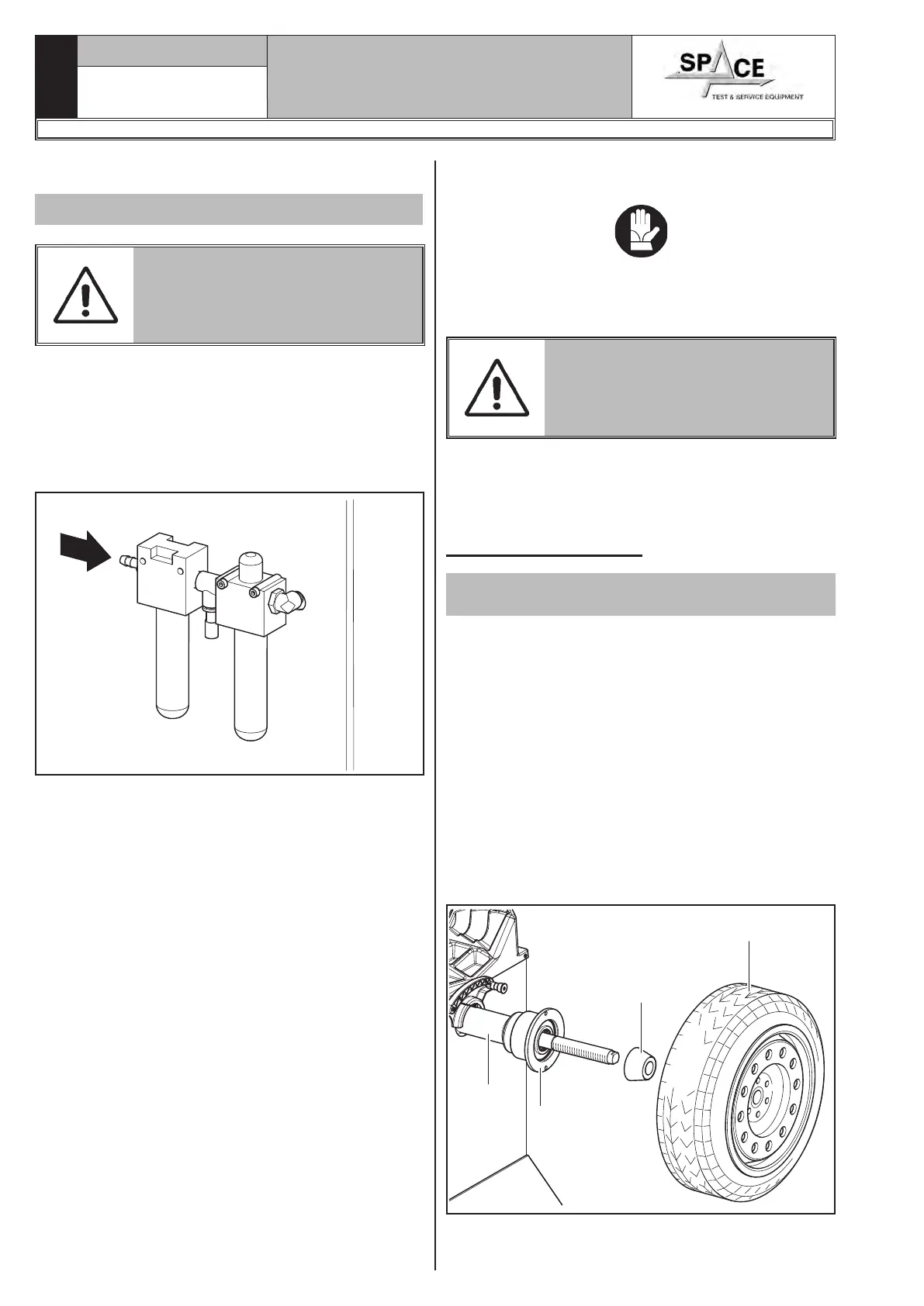
11.0 AIR CONNECTIONS
Only for ERP248R models
IN CASE OF A CHANCE SUP-
PLY FAILURE, AND/OR BEFORE
ANY PNEUMATIC CONNECTIONS,
MOVE THE CONTROLS TO THE
NEUTRAL POSITION.
Connect the wheel balancer to the centralised com-
pressed-air system by means of the connection on the
back of the machine (see Fig. 25).
The air system supplying the machine must be able
to supply filtered and de-humidified air at a pressure
between 8 and 10 bar. It must feature an on-off valve
upstream of the machine.
Fig. 25
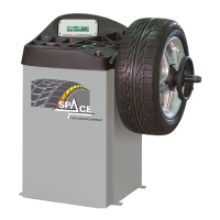
12.0 FITTING THE WHEEL ON THE
MANDREL
To achieve perfect balancing, the wheel must be care-
fully and properly fitted on the mandrel. Imperfect
centring will inevitably cause unbalances.
MOST IMPORTANT IS THAT ORIGI-
NAL CONES AND ACCESSORIES
ARE USED MADE SPECIFICALLY
FOR USE ON THE WHEEL BAL-
ANCER.
Wheel fitting using the cones provided is illustrated
below.
For alternative fittings, using optional accessories, refer
to the special instructions provided separately.
12.1 Wheel assembly
Only for ER232R - ER234R - ER236R - ER238R
- ER238RFM - ER248R
1. Remove any type of foreign body from the wheel
(Fig. 26 ref. 3): already-existing weights, stones
and mud, and make sure the shaft (Fig. 26
ref. 1):and the rim centring area are clean before
fitting the wheel on the shaft.
2. Carefully choose the cone (Fig. 26 ref. 2) most suit-
able for the wheel to be balanced. These accessories
must be selected according to the shape of the rim.
Carefully position the wheel (Fig. 26 ref. 3), fit-
ting the cone (Fig. 26 ref. 2) on the shaft (Fig. 26
ref. 1) (otherwise this could seize) until this rests
against the support flange (Fig. 26 ref. 4).
3. Fit the wheel with the inner side of the rim towards
the wheel balancer and against the cone.
1
2
3
4
Fig. 26