GB
Page 22 of 58
INSTRUCTION, USE AND
MAINTENANCE MANUAL
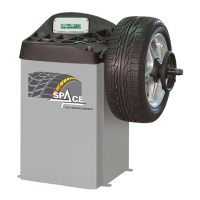
Fig. 29
1
2
3
1
THE GRIP-RING (FIG. 29 REF. 1)
MUST BE MOUNTED WITH THE
TEETH SIDE TOWARDS THE RING-
NUT (FIG. 29 REF. 2).
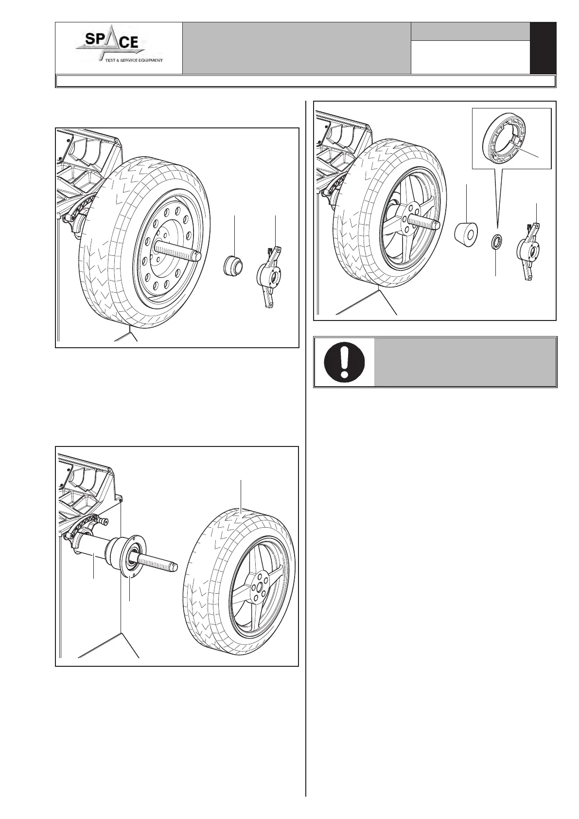
4. Fit the protection cap (Fig. 27 ref. 1) in the locknut
(Fig. 27 ref. 2) and fasten against the wheel.
Fig. 27
1
2
Some aluminium wheels, with very high centring, must
be fitted with the cone outside the wheel.
5. Clean the shaft (Fig. 28 ref. 1) before fitting the
wheel.
6. Fit the wheel (Fig. 28 ref. 3) with the inside of the
rim towards the wheel balancer, until the wheel is
up against the support flange (Fig. 28 ref. 2).
3
1
2
Fig. 28
7. Fit the cone (Fig. 29 ref. 3) with the narrowest part
turned towards the wheel.
8. Fit the grip-ring (Fig. 29 ref. 1) in the nut (Fig. 29
ref. 2) and fasten the cone (Fig. 29 ref. 3).
1296-M010-0_P
Space s.r.l.
ER232R - ER234R - ER236R - ER238R - ER238RFM - ER248R - ERP248R