GB
Page 24 of 58
INSTRUCTION, USE AND
MAINTENANCE MANUAL
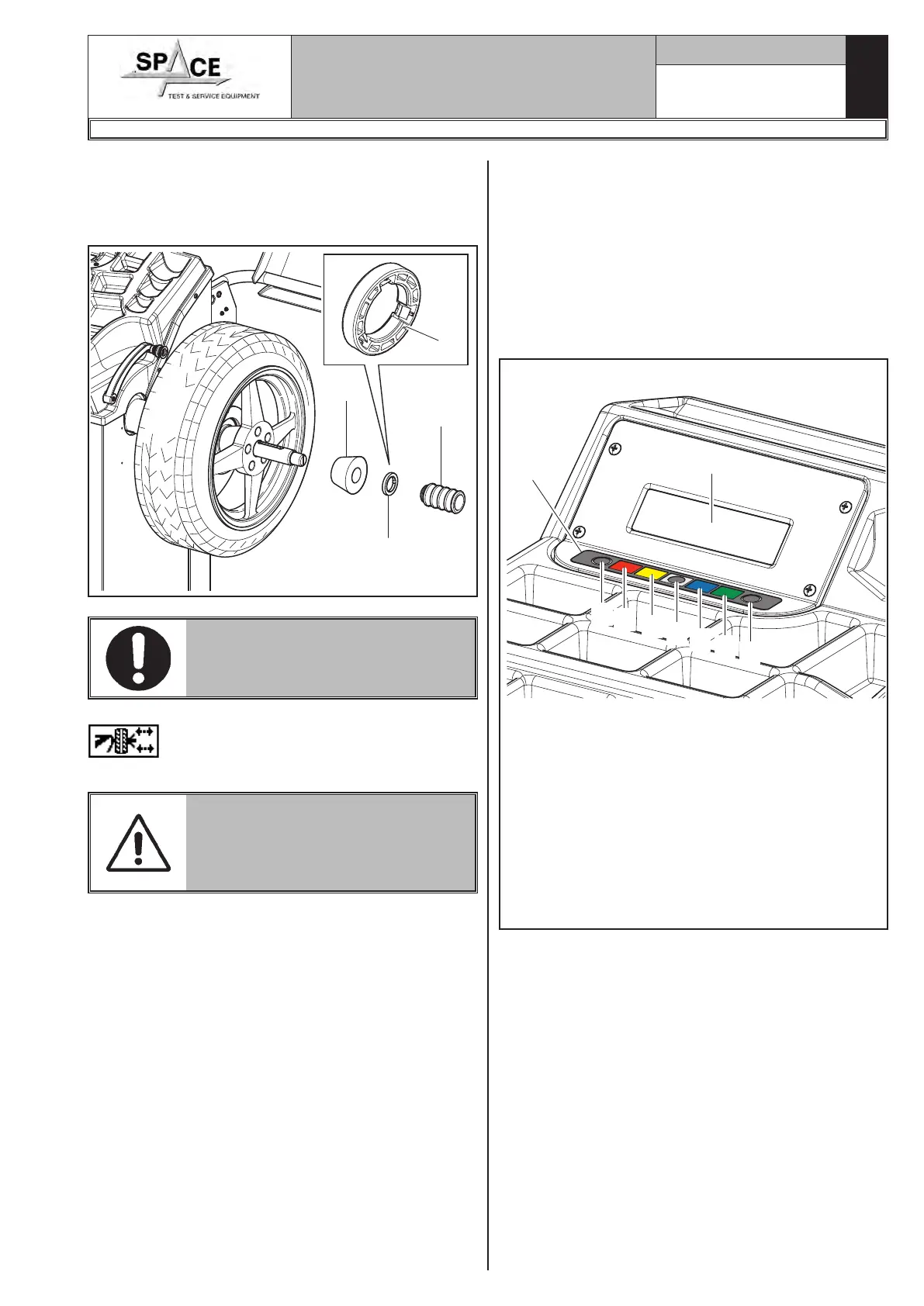
13.0 DISPLAY WITH KEYBOARD
The wheel balancers are equipped with a multifunction
LCD display, equipped with a keyboard to interact/
operate the controls present in graphical form on the
same display.
On such display are displayed all the instructions for
the correct wheel balancing, for example indicating
where the operator shall fit adhesive or clip weights and
the balancing mode and/or option used, as well as cor-
rect wheel rotation for inner/outer weights positioning.
1
9
6
5
4
3
2
7
8
Fig. 35
KEY
1 – Display
2 – Function push button (red)
3 – Function push button (yellow)
4 – Function push button (grey)
5 – Function push button (blue)
6 – Function push button (green)
7 – Previous page push button
8 – Next page push button
9 – Push-button panel (push-button panel with 7
keys)
7. Fit the cone (Fig. 34 ref. 3) with the narrowest part
turned towards the wheel.
8. Fit the grip-ring (Fig. 34 ref. 1) in the bush (Fig. 34
ref. 2) and bring everything against the wheel.
Fig. 34
1
2
3
1
THE GRIP-RING (FIG. 34 REF. 1)
MUST BE MOUNTED WITH THE
TEETH SIDE TOWARDS THE BUSH
(FIG. 34 REF. 2).
Close the pneumatic mandrel by pressing “key F4”
from the configuration screen play (Fig. 87),
or else close by means of the special pedal.
DURING MANDREL OPENING/
CLOSING OPERATIONS, BE CARE-
FUL TO KEEP YOUR HANDS AND
OTHER PARTS OF THE BODY
AWAY FROM THE MANDREL.
1296-M010-0_P
Space s.r.l.
ER232R - ER234R - ER236R - ER238R - ER238RFM - ER248R - ERP248R