GB
Page 50 of 58
INSTRUCTION, USE AND
MAINTENANCE MANUAL
Fig. 94
1
KEY
1 – Return to previous screen page (RED) (F1)
2 – "Zero chucking-table" setting without anything.
This operation must necessarily be performed
after setting the weight sensor machine calibra-
tion (CENTRAL)
3 – Perform weight sensor machine calibration
(BLUE) (F3)
2 3
Fit a wheel of medium size, possibly balanced (Ø
=13÷14”, L = 4÷5”).
From the calibration page menu (see Fig. 94) press
the weight sensor calibration “F3 key”; the program
will display the following image:
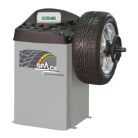
Fig. 95
1
KEY
1 – Return to previous screen page (RED) (F1)
2 – Decrease wheel dimension values (YELLOW)
(F2)
3 – Select and confirm the values to be set (CEN-
TRAL)
4 – increase wheel dimension values (BLUE) (F3)
5 – Display next image (GREEN) (F4)
3 4 52
1296-M010-0_P
Space s.r.l.
ER232R - ER234R - ER236R - ER238R - ER238RFM - ER248R - ERP248R
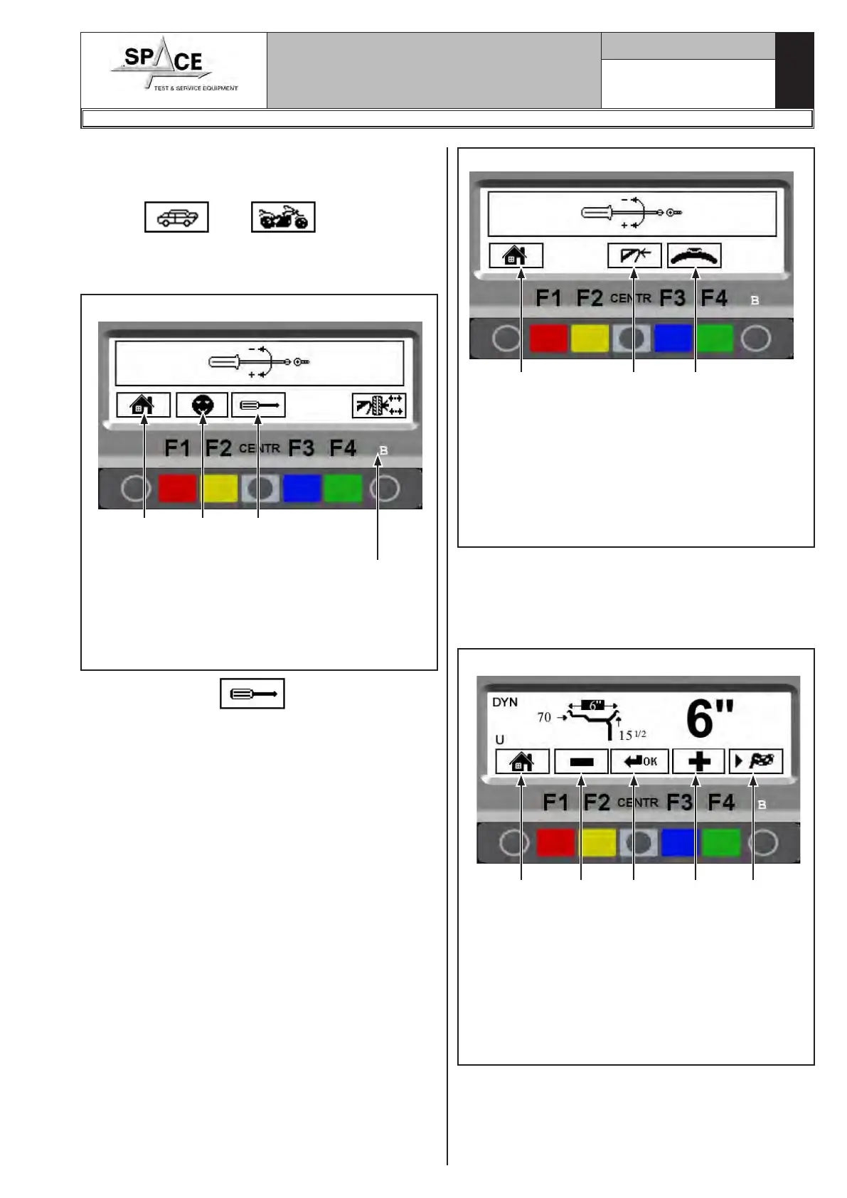
21.0 WHEEL BALANCER CALIBRATION
From program presentation screen page, when the
machine is set to CAR or MOTORCYCLE mode (the
symbol “
” or “ ” appears on the
screen, see Fig. 37) press “F1 key ” and enter the
password F1-F2-CENTR-F3.
The program will display the following image:
Fig. 93
1
KEY
1 – Return to initial program page (RED) (F1)
2 – Configuration (YELLOW) (F2)
3 – Calibrations (CENTRAL)
4 – Open/Close the pneumatic mandrel (GREEN)
(F4) (models ERP248R only)
2 3
Press key “CENTR” and the program will
display the following figure:
4