INSTRUCTION, USE AND
MAINTENANCE MANUAL
GB
Page 17 of 58
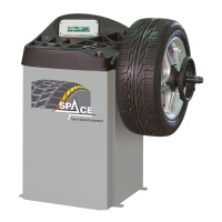
3. Make sure the gauge tip is positioned at the centre
of the mandrel (Fig. 16 ref. 1).
1
Fig. 16
4. Connect connector (Fig. 17 ref. 1) of the cable com-
ing from inside the machine to connector (Fig. 17
ref. 2) of the cable coming from the gauge arm. Fit
the section of the cable with the connectors inside
the arm (Fig. 17 ref. 3).
5. Fasten the cable with clamps.
6. Enable the external data gauge and carry out the
device's calibration.
1
2
3
Fig. 17
1296-M010-0_P
Space s.r.l.
ER232R - ER234R - ER236R - ER238R - ER238RFM - ER248R - ERP248R
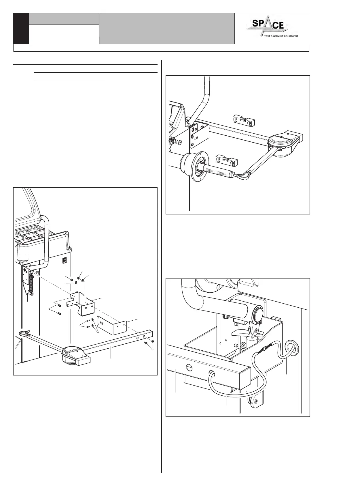
9.3.4 Fitting of GAR301 automatic external
data gauge (optional for ER236R -
ER238R - ER238RFM)
1. Unscrew the 2 screws (in vertical position) of the pro-
tection guard support (Fig. 15 ref. 1) (if present)
being very careful about holding the same support.
2. Introduce the 2 screws (Fig. 15 ref. 2) to the gauge
bracket (Fig. 15 ref. 3) and screw them onto the
special threaded inserts placed on the rear side of
the frame. Fasten the bracket (Fig. 15 ref. 4) to the
protection guard support with the washers (Fig. 15
ref. 5) and the 2 screws (Fig. 15 ref. 6).
Lock the gauge arm (Fig. 15 ref. 7) to the brack-
ets (Fig. 15 ref. 34) using the 2 screws (Fig. 15
ref. 8), the washers (Fig. 15 ref. 9) and the nuts
(Fig. 15 ref. 10), so that the shaft and the gauge
arm are levelled (see Fig. 16).
1
2
3
4
5
6
7
8
9
10
9
10
Fig. 15