INSTRUCTION, USE AND
MAINTENANCE MANUAL
GB
Page 43 of 58
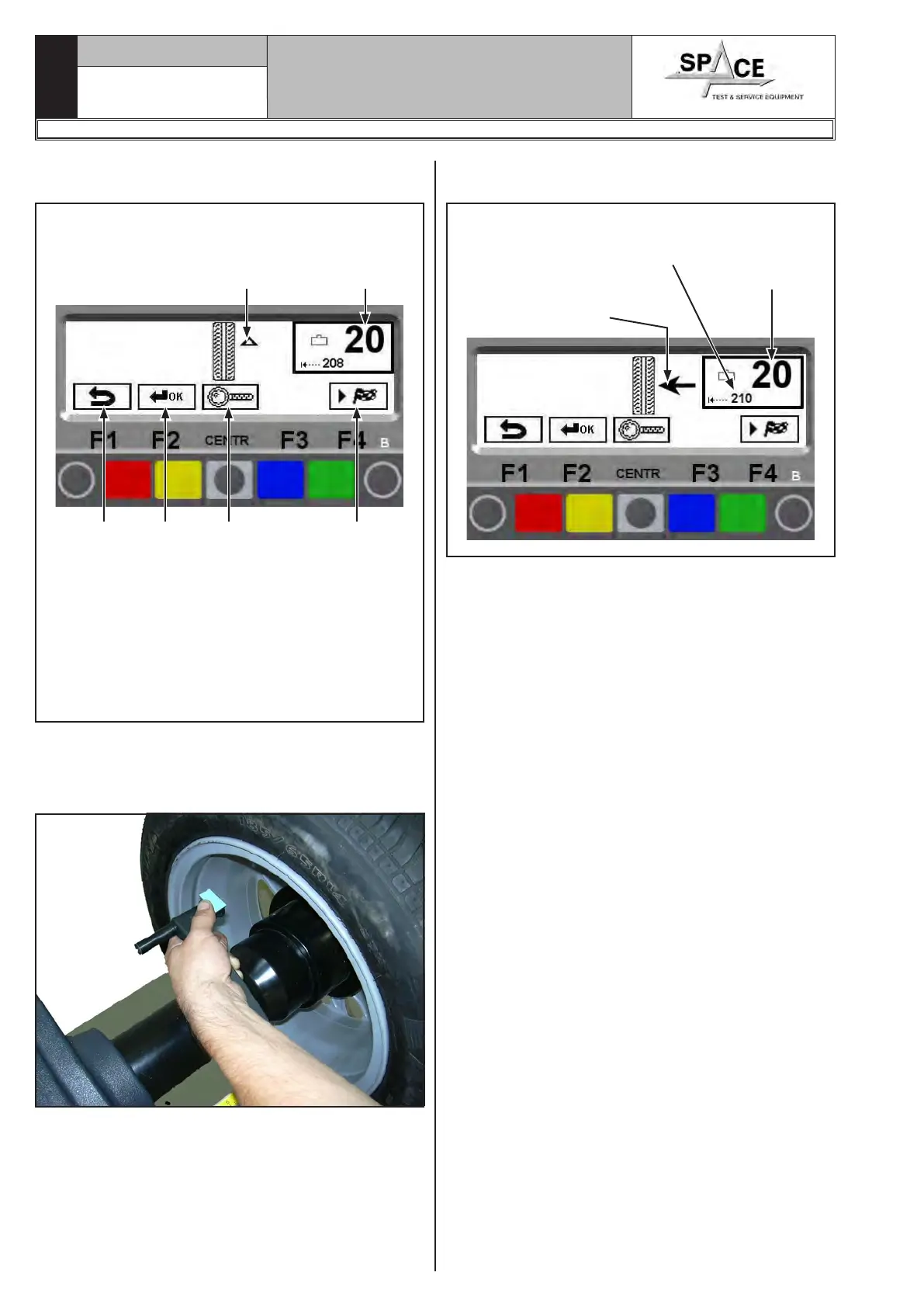
The machine automatically calculates weight position
in two positions hidden behind the spokes.
Fig. 76
KEY
1 – Return to previous screen page (RED) (F1)
2 – Return to initial unbalance screen page (YEL-
LOW) (F2)
3 – Displays exact unbalance (pitch 1 g instead of 5
g) (CENTRAL)
4 – Confirm and continue second weight positioning
(GREEN) (F4)
1 3 4
Total weight
Arrows to help positioning
in correction weight fitting
point
2
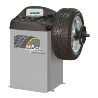
Correctly position the wheel (see Par. 15.3.2) and
lock it
Fit the adhesive weight (in the example this is 20g) in
the manual distance caliper as shown in Fig. 77.
Fig. 77
Fit the adhesive weight inside the spoke at the point
indicated on the display screen in Fig. 78.
Fig. 78
Exact weight fitting dis-
tance inside the spoke
Exact position of
wheel for fitting
weight
Required weight
Correctly position the wheel (see Par. 15.3.2) and lock
it and fit the second adhesive weight in the manual
distance caliper as shown in Fig. 77.
Fit the adhesive weight inside the spoke at the point
indicated on the display screen in Fig. 78.
Press the “F4 key" to confirm positioning of second
weight behind the spoke.
The system displays the initial unbalance situation
before performing the SPOKES procedure.
1296-M010-0_P
Space s.r.l.
ER232R - ER234R - ER236R - ER238R - ER238RFM - ER248R - ERP248R