- 38 -
z Select alarm input channel for apply record setting. Select [ALL] for apply to all channels.
5.6.2 Alarm Input Type
The alarm input attribution includes N/O. and N/C.
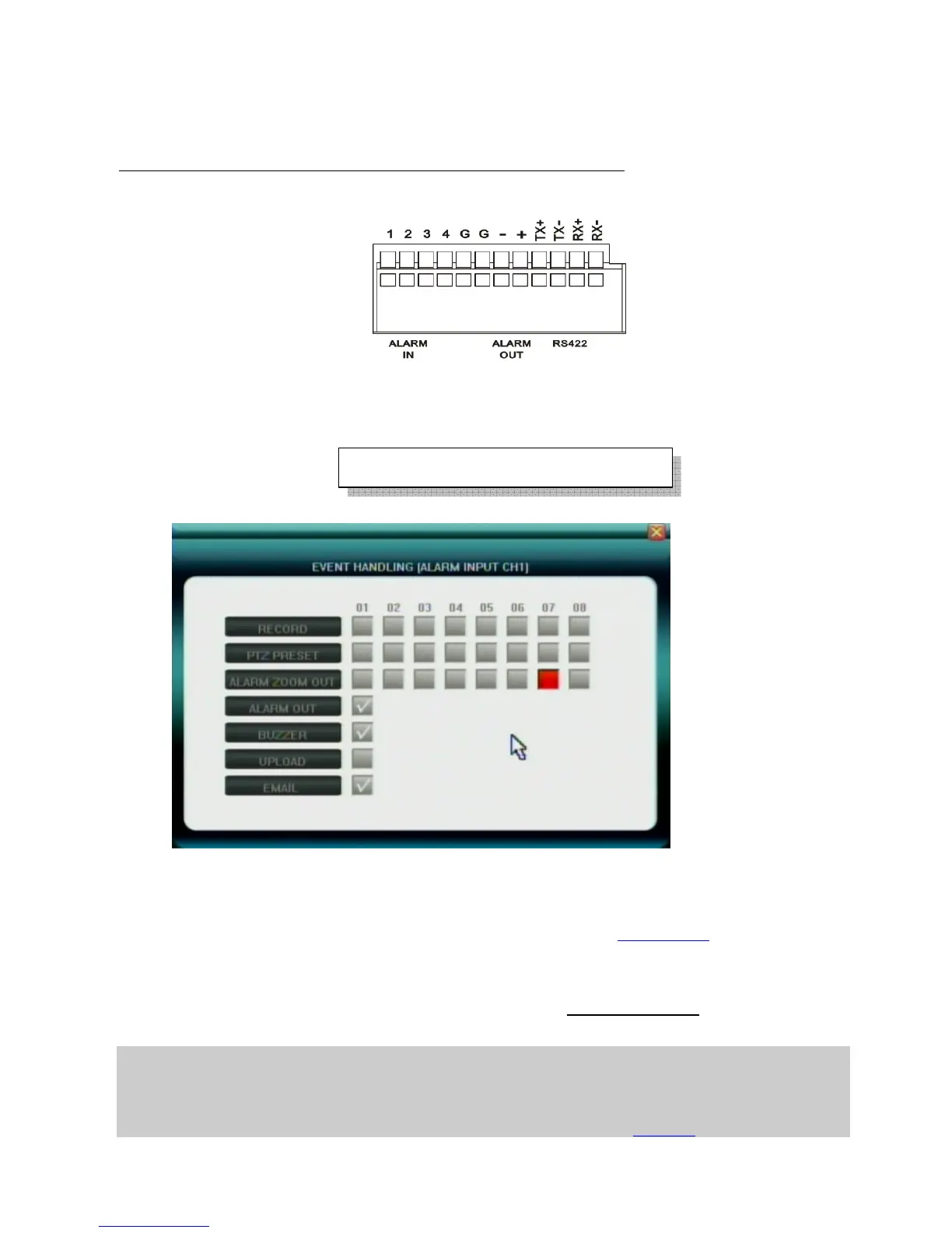
Each camera has one input pin on Terminal Block at the real panel.
User must use voltage output type sensor to connect alarm input interface
.
Sensor device output POSITIVE (+) pin connect to DVR’s input pin (1~4 pin)
Sensor device output GROUND (-) pin connect to DVR’s G pin (5~6) pin
N/O.: Normally open. Sensor must constant output low level voltage. If output voltage change from Low
level to High level then DVR will be triggered.
N/C.: Normally connected. Sensor must constant output High level voltage. If output voltage change from
High level to Low level then DVR will be triggered.
5.6.3 Event Handling
User can pre-define correspond actions while DVR handling the Alarm event.
z Record: Start record immediately for selected channels
z PTZ PRESET: set up the PTZ preset position for selected channels
z Alarm Zoom Out: Set the pop up selected channels, please refer to Chapter 5.6.4
z Alarm Out: Set the Alarm output enabled
z Buzzer: Set the internal Buzzer enable
z Upload: upload these events message to IE or CMS server, to be displayed at the top right corner
z E-mail: Send E-mail with Snapshot picture(please refer to 5.5.6 E-mail Server
about how to set up
the E-mail address list)
Note1: if user wants to set alarm triggered record, please set the record schedule first at “Record Schedule”.
Note2: if user wants to set alarm triggered PTZ, please select the channel number first, and then to set (only preset 1 can be selected)
Note3: Event handling sound / report to alarm center need to be set in IE explorer. Please refer to Chapter 6.3
Maximum high level voltage is 5V
DC