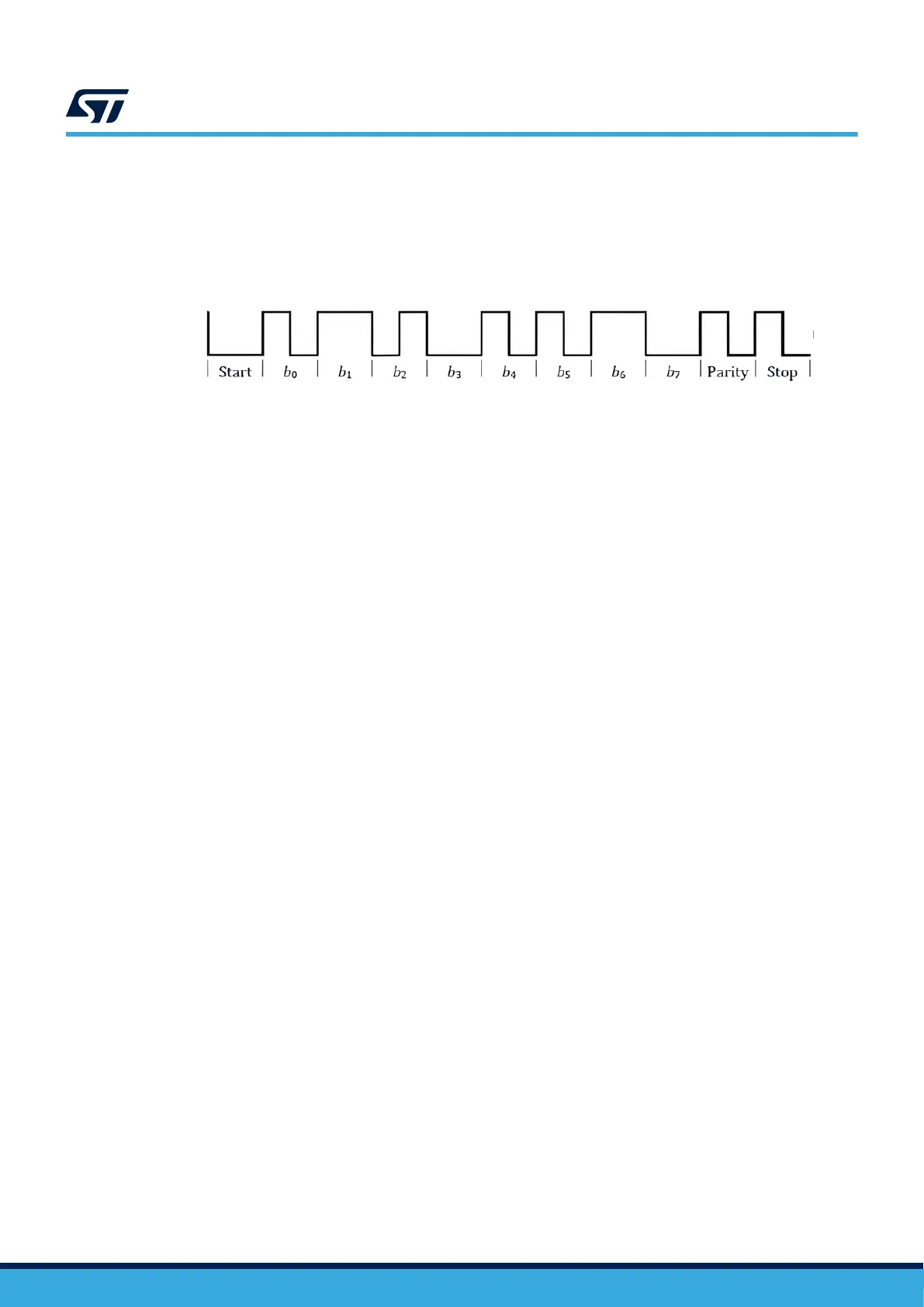
To transmit a single byte of data, the power receiver must send an 11-bit sequence. This sequence consists of a
START bit (ZERO), the 8 data bits of the byte (LSB first), a parity bit and a STOP bit (ONE). The parity is odd,
meaning an even number of ONE bits in the data byte results in the parity bit being equal to ONE, while an odd
number of ONE bits in the data byte results in the parity bit being equal to ZERO. An example of such a message
can be seen in the picture below:
Figure 9. Example of byte encoding
A packet consists of a preamble, header, message, and checksum. The preamble contains 11 to 25 ONE bits
and enables the power transmitter to synchronize with the incoming data. The header, message, and checksum
are sequence of three or more bytes. The header indicates the packet type while also implicitly providing the size
of the message. The checksum consists of a single byte. It is calculated as an exclusive or of both the header and
message bytes and enables the power transmitter to check for transmission errors.
For a more detailed explanation refer to the Qi specification, section Power Receiver to Power Transmitter
communications interface.
4.12.2 FSK communication
The power transmitter modulates the power signal by switching between its normal operating frequency f
op
and its
modulated frequency f
mod
. The difference between f
op
and f
mod
can be described by two parameters: polarity
and depth.
Polarity is given by the difference between f
mod
and f
op
- a positive polarity corresponds to a positive difference,
while a negative polarity corresponds to a negative difference.
Depth describes the magnitude of difference between f
op
and f
mod
. Please note that a negative polarity results in
a higher induced voltage on the power receiver coil and should therefore be used with care.
The FSK communication is executed via packets. Each packet consists of three parts - a header, a message, and
a checksum. The header is a single byte, which indicates the packet type, while also implicitly providing the size
of the message part. The message size can range from 1 up to 27 bytes. The checksum is a single byte, which
provides a way to check for transmission errors. It is calculated as an exclusive or of the header bytes and the
message bytes.
Each FSK bit is aligned to 512 periods of the power signal. A ONE bit is represented by two transitions over the
512-period slot - the frequency change occurs at the very start of the slot and after 256 power signal periods
pass. A ZERO bit is represented by a single transition (at the start of the 512-period slot).
Each data byte is transferred as a sequence of 11 bits. The sequence consists of a start bit (ZERO), the data byte
itself, a parity bit and a stop bit (ONE). The parity used for byte encoding is even - the parity bit is set to a ONE if
the data byte contains an odd number of ONE bits. If the data byte contains an even number of ONE bits, the
parity bit is set to a ZERO instead. This encoding scheme is used for all three parts of the FSK packet - the
header, message, and checksum.
There is also an additional type of message, which can be sent from the transmitter to the receiver: a response to
a receiver’s message. A response consists of 8 bits, so the receiver can use quite a simple logic to decode it. The
response can be either Acknowledge (ACK), Not-Acknowledge (NAK), Not-Defined (ND), or Attention (ATN):
• ACK is encoded as a series of 8 ONE bits
• NAK is encoded as 8 zero bits
• ND is encoded as a series of 8 bit of alternating ZERO and ONE bits ('01010101')
• ATN is defined as alternating pairs of ZERO and ONE bits ('00110011')
UM3286
Device description and operation
UM3286 - Rev 1
page 16/84