5 Graphical user interface (GUI)
STWBC2 can be configured using STSW-WBC2STUDIO. The GUI can also be used to monitor and program the
device.
5.1 Connecting STWBC2 to the GUI
Step 1.
Connect the STLINK-V3MINIE bridge to a PC by USB cable.
Step 2. Connect the STEVAL-WBC2TX70 board, connector J203 to STLINK-V3MINIE bridge by a flat cable.
Step 3. Power up the STEVAL-WBC2TX70.
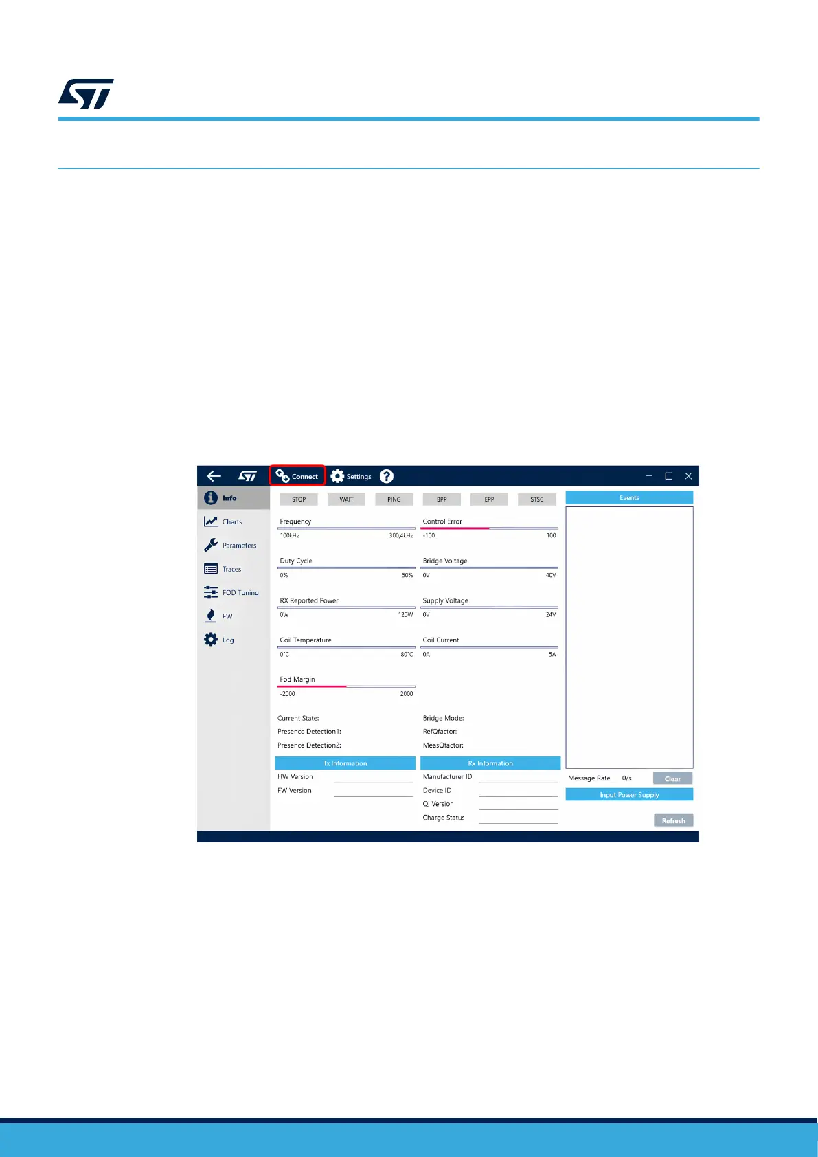
Step 4. Open the GUI on your PC. Click the [Connect] button in the top menu.
Note: Communication between the GUI and the board can be established only after startup of the board is finished.
The startup pending status is indicated by both (RED and GREEN) LEDs ON. This process only takes several
seconds. When the LEDs turn OFF, the device is ready. If you try to connect to the device when it is not ready,
the GUI raises an error message.
Figure 16. The initial state of the GUI
If a supported bridge is used, the GUI automatically detects the proper COM port number. Otherwise, the COM
port number can be manually chosen in the
[Settings] menu.
Note: For the first firmware load, it is possible to connect to a chip even if it does not have firmware loaded.
UM3286
Graphical user interface (GUI)
UM3286 - Rev 1
page 27/84