7.2.3 Board input layout
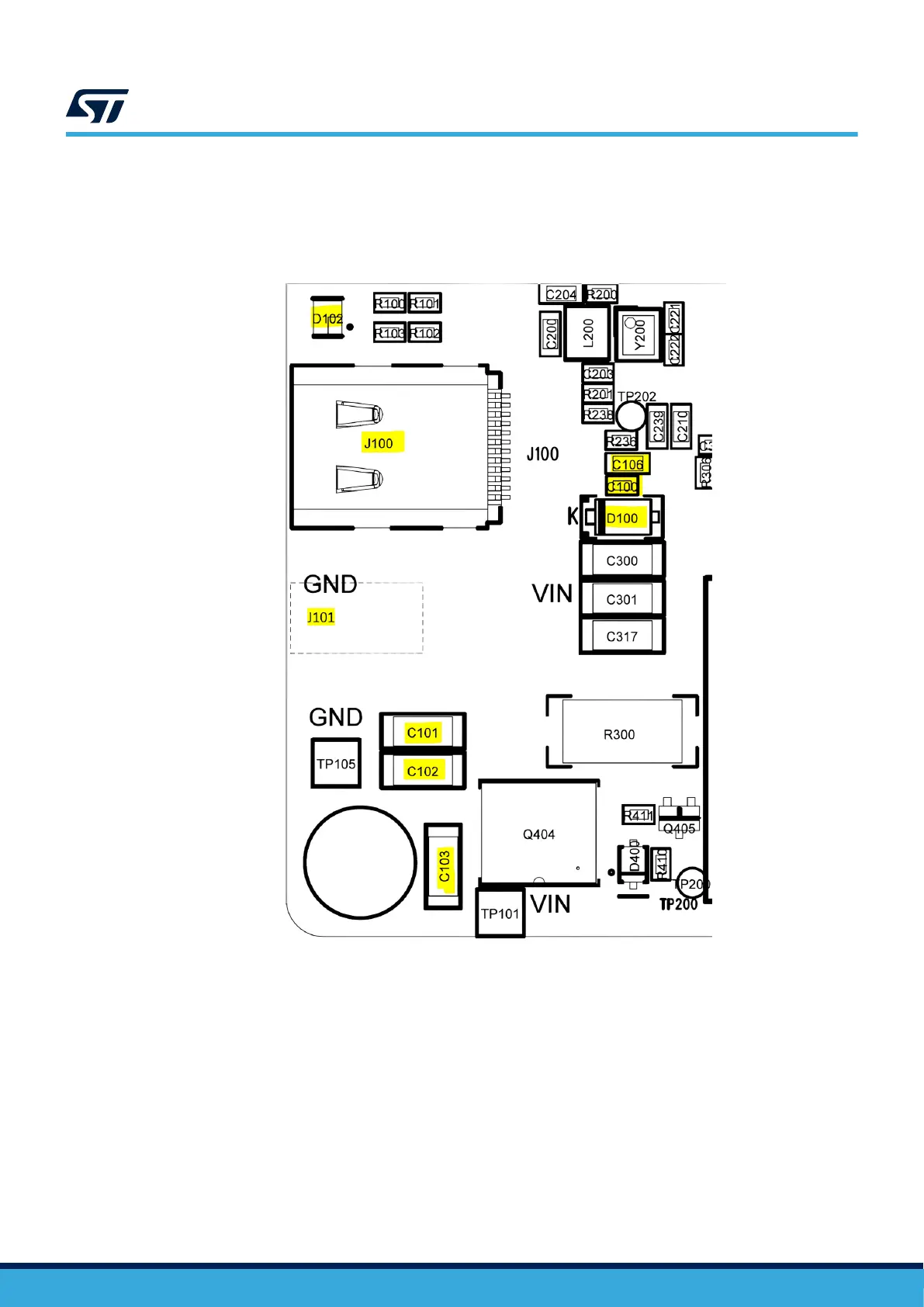
USB Type-C® and barrel jack connectors are placed closely together. The TVS diodes and the input capacitors
are placed close to the input connectors and the layer 1 ground plane is connected to the other ground planes
through multiple vias.
Figure 50. Placement of input connectors, filtering, and protections
Note: Barrel jack connector J101 is placed on the bottom side of the board.
UM3286
Designing a wireless power transmitter based on STEVAL-WBC2TX70 evaluation board
UM3286 - Rev 1
page 66/84