6.3.2 Board power supply - Hardware configuration
The power supply is configured by setting the related jumpers JP3, JP29 and JP37 as described in Table 9.
Table 9. Power related jumpers
Jumper
Description
(1)
JP3
JP3 is used to measure current consumption manually with a multimeter.
ON
JP29
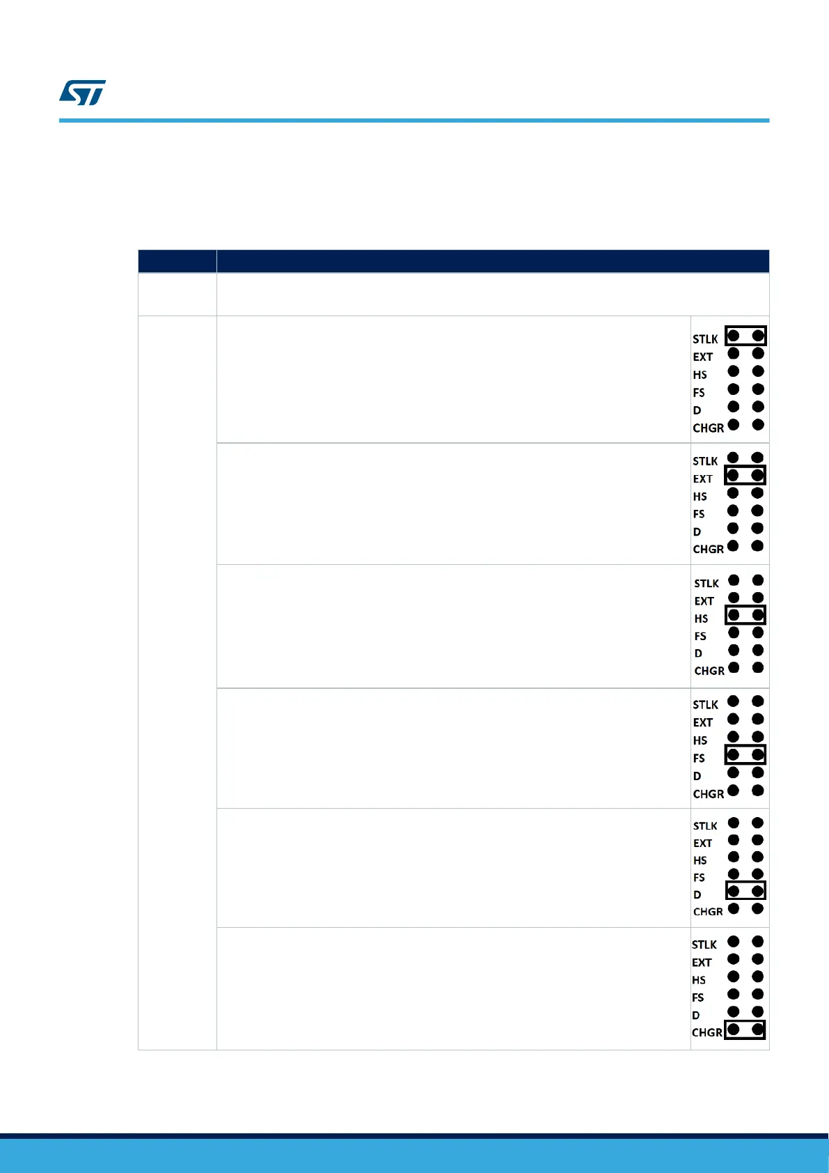
JP29 is used to select one of the six possible power supply resources:
For power supply from USB connector of STLINK-V3E (CN21) to
STM32H7B3I-EVAL, JP29 is set as shown on the right.
For power supply jack(CN17) to the STM32H7B3I-EVAL,
JP29 is set as shown on the right.
For power supply from USB OTG HS (CN14) to STM32H7B3I-EVAL,
JP29 is set as shown on the right.
For power supply from USB OTG FS (CN27) to STM32H7B3I-EVAL,
JP29 is set as shown on the right.
For power supply from the daughterboard connectors (CN5 and CN6)
to STM32H7B3I-EVAL, JP29 is set as shown on the right.
For power supply from a USB wall charger plugged to CN21
to STM32H7B3I-EVAL, JP29 is set as shown on the right.
UM2662
Power supply
UM2662 - Rev 1
page 17/95