Find CN11 (Right) pin-out in Table 58.
Table 58. CN11 (Right) MB1242 pin-out
Pin
number
Description Pin connection
Pin
number
Description Pin connection
1 3V3_AO 3V3_AO 2 3V3_AO 3V3_AO
3 3V3_AO 3V3_AO 4 3V3_AO 3V3_AO
5 NC NC 6 NC NC
7 NC NC 8 NC NC
9 NC NC 10 NC NC
11 NC NC 12 NC NC
13 RFU2 test point NC 14 RFU1 test point NC
15 RSTOUTn test point NC 16 INTn test point NC
17 GND GND 18 GND GND
19 GND GND 20 GND GND
8.7 CAN FD
8.7.1 Description
The STM32H7B3I-EVAL Evaluation board supports one channel of flexible data rate CAN, CAN‑FD compliant bus
communication based on 3.3 V CAN transceiver.
To use CAN FD, fit SB36 and SB35 solder bridges (And remove these solder bridges when using USB OTG FS,
to avoid stubs).
Standby signal on CAN‑FD transceiver is controlled by MFX IO9.
8.7.2 Operating voltage
STM32H7B3LIH6QU CAN‑FD interface can only be at 3.3 V on this board. The CAN‑FD MCP2562FDT-H/SN
transceiver (U28) requires 5 V on the VDD pin.
8.7.3 Limitations and hardware configuration
Limitation with primary function USB OTG FS
8.7.4 Interface
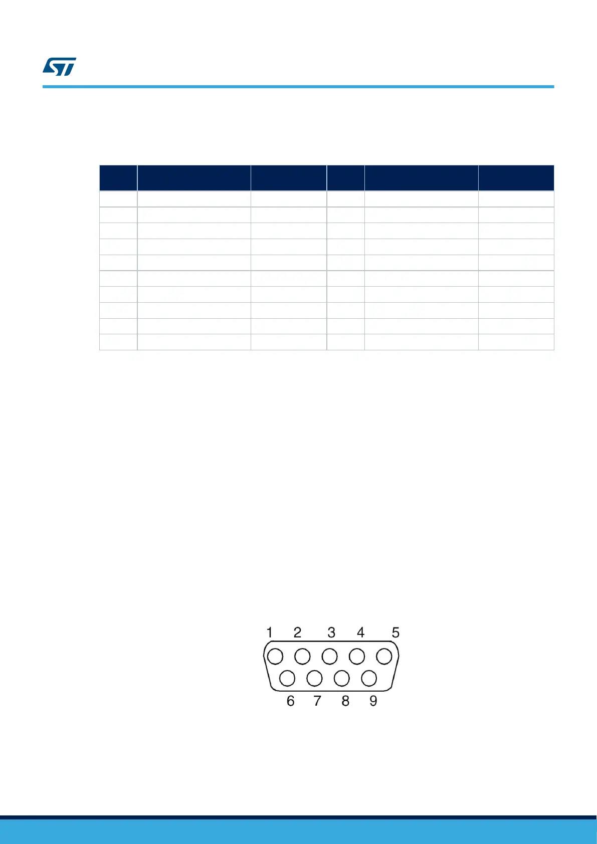
Figure 33. CAN D-type 9-pin male connector CN22
UM2662
CAN FD
UM2662 - Rev 1
page 61/95