Pin number Description Pin connection
40 GND GND
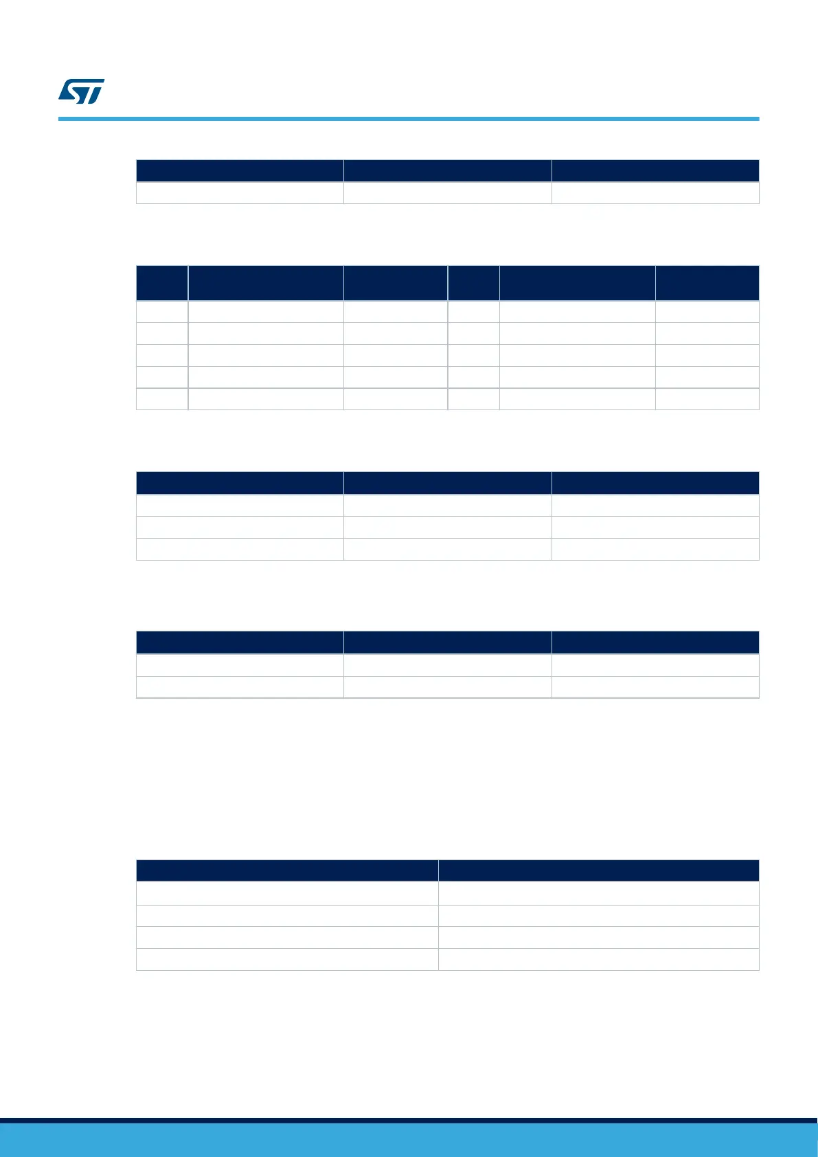
Table 36. CTP and LCD power connector CN30
Pin
number
Description Pin connection
Pin
number
Description Pin connection
1 GND GND 2 3V3_AO 3.3V
3 CTP I2C2 SDA PH5 4 5V 5V
5 CTP I2C2 SCL PH4 6 5V 5V
7 GND GND 8 GND GND
9 CTP RST PC4 (not used) 10 CTP INT PH2
Table 37. LCD RESET hardware configuration
Signal name
R125
(1)
R126
(1)
LCD_RESET = NC OFF OFF
LCD_RESET = NRST ON OFF
LCD_RESET = PA2 OFF ON
1. The default setting is in bold.
Table 38. CTP RESET hardware configuration
R155
(1)
R156
(1)
CTP_RST = NRST ON OFF
CTP_RST = PC4 OFF ON
1. The default setting is in bold.
7.10
LEDs and buttons
7.10.1 Description
Four general-purpose color LEDs (LD1, LD2, LD3, and LD4) are available as display devices.
Table 39. LCD module connector CN23
Pin name LED name
PG13
(1)
LED1
MFX IO11 LED2
MFX IO12 LED3
MFX IO13 LED4
1. PG13 pin is supplied by VDDMMC. Make sure to supply 3.3 V on VDDMMC (Refer to Section 6.3.5 ).
UM2662
LEDs and buttons
UM2662 - Rev 1
page 42/95