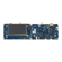
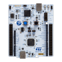
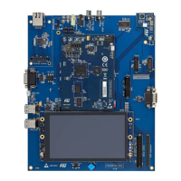
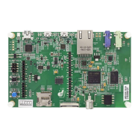
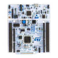
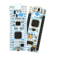
The Wakeup B2 and Tamper/key B3 buttons3 are available as input devices.
Table 40. B2 and B3 buttons
Pin name Button name
PA0 B2 (KEY_WKUP0)
PC13 B3 (KEY_TAMP_1/WKUP2)
7.10.2 Operating voltage
STM32H7B3LIH6QU LEDs and buttons interface can only be at 3.3 V on this board. For LED1, make sure to
supply 3.3 V on VDDMMC (Refer to Section 6.3.5 ).
7.11 Camera module MB1379
7.11.1 Description
The MB1379 camera module is connected to STM32H7B3LIH6QU DCMI and I
2
C interface through CN2. This
module embeds an HDF5640-AF-V2.0 module with an OmniVision OV5640 1/4" color CMOS QSXGA (5
megapixel) camera sensor.
7.11.2 Operating voltage
STM32H7B3LIH6QU DCMI camera interface can only be at 3.3 V on this board. I
2
C is at 2.8 V on the camera
side and therefore requires the use of level shifters Q1 and Q2. Make sure to supply 3.3 V on VDDMMC (Refer to
Section 6.3.5 )
7.11.3 Limitations and hardware configuration
Limitation with primary functions: audio I2S6 and DFSDM (Refer to the jumper configuration in Table 41).
Limitation with secondary functions: microSD
™
card 2, SAI, USB HS, MEMS LED, NOR and OCSPI2.
I2C2 (PH4/PH5) is shared between EXT I
2
C module CN24, MB1486 Wi‑Fi
®
module U24, MFX I/O expander U25,
audio codec U48, MB1379 camera module CN2, and MB1370 LCD touch panel CN30.
UM2662
Camera module MB1379
UM2662 - Rev 1
page 43/95

 Loading...
