6.2 External JTAG, SWD, and trace
6.2.1 Description
There are two basics ways to support an external debug tool. If the user encounters any trouble with the first
procedure, then the second one is mandatory.
1. Keep the embedded STLINK-V3E running. Power on the STLINK-V3E at first until the COM LED lights RED.
Then connect the external Debug tool through connector CN14, CN15 or CN16.
2. Set the embedded STLINK-V3E in a high impedance state. When the Jumper CN19 (STLK NRST) is ON,
the embedded STLINK-V3E is in RESET state and all GPIOs are in high impedance; then the user can
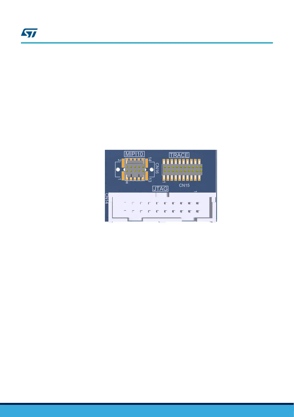
connect his external Debug tool on the DEBUG connector CN14, CN15, or CN16 (Refer to Figure 5).
Note: Depending on the design requirement, the embedded STLINK-V3E hardware may be completely disconnected if
that is required early in the project.
Figure 5. External debug tools connectors
Remarks:
• It is possible to power the board via CN21 (Embedded STLINK-V3E USB connector) even if an external tool
is connected to CN15 (ETM trace connector) or CN14 (External JTAG and SWD connector).
• ETM can only work at 50 MHz clock frequency by default because ETM signals are shared with other
peripherals.
UM2662
External JTAG, SWD, and trace
UM2662 - Rev 1
page 11/95