7.4.2 Operating voltage
The STM32H7B3LIH6QU microSD
™
card interface can only be at 3.3 V on this board.
7.4.3 Limitations and hardware configuration
Fit JP15 to connect SD_DETECT1 to the STM32H7B3LIH6QU PF10 pin, and fit JP12 [1-2] to connect SDIO1_D0
to STM32H7B3LIH6QU PC8 pin.
7.4.4 Interface
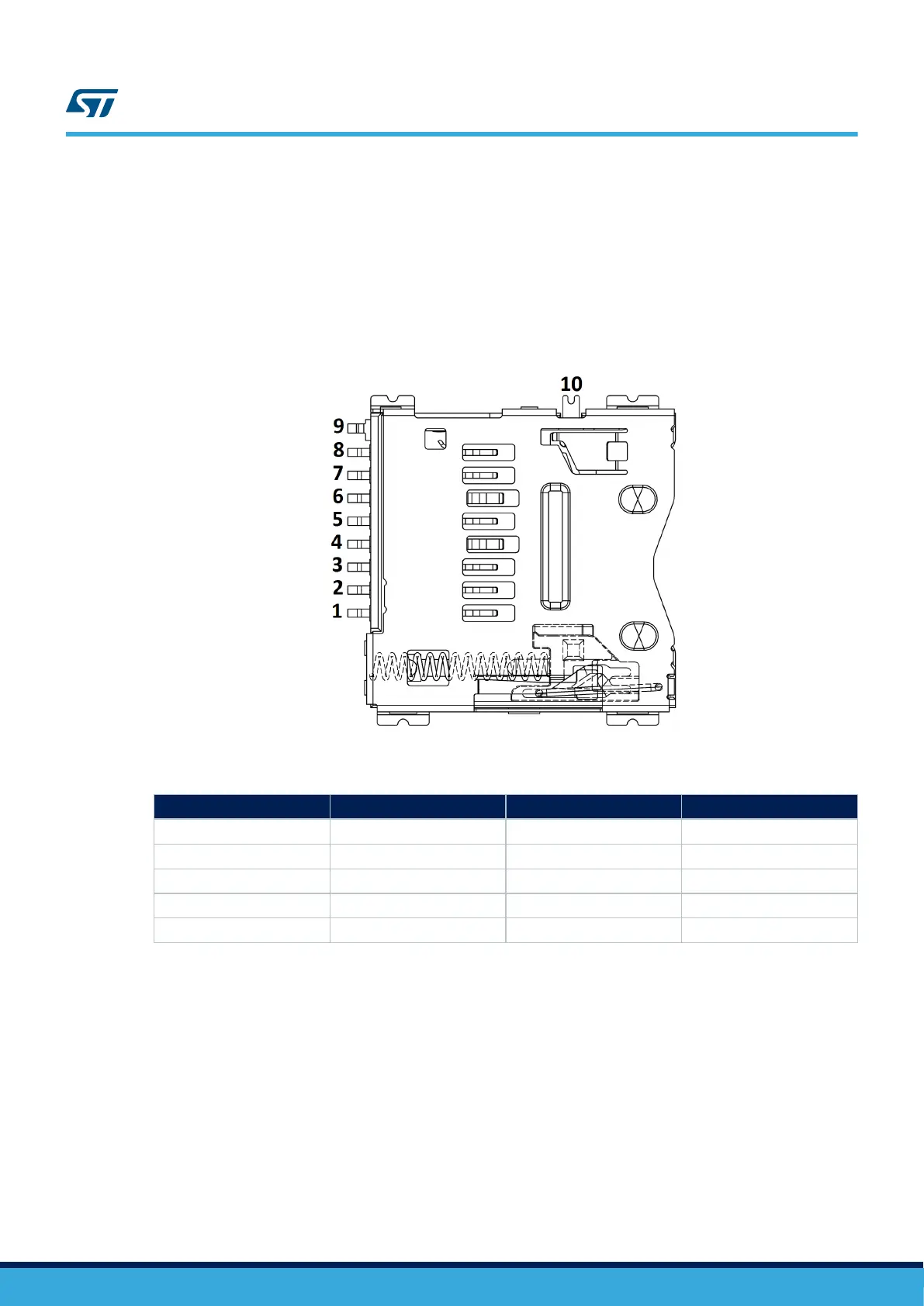
Figure 25. microSD
™
connector CN28
Table 30. microSD
™
connector CN28
Pin number
Description Pin number Description
1 SD_DATA2 (PC10) 6 VSS / GND
2 SD_DATA3 (PC11) 7 SD_DATA0 (PC8)
3 SD_CMD (PD2) 8 SD_DATA1 (PC9)
4 3V3_AO 9 GND
5 SD_CLK (PC12) 10 Micro SDcard_detect (PF10)
7.5
EXT I
2
C connector
7.5.1 Description
I2C2 bus of STM32H7B3LIH6QU is connected to CN24 on STM32H7B3I-EVAL. The I
2
C functional
daughterboard can be mounted on CN24 and accessed by the microcontroller via the I2C2 bus.
EXT_RESET is controlled by MFX_GPO6 signal.
7.5.2 Operating voltage
The STM32H7B3LIH6QU EXT I
2
C connector can only be at 3.3 V on this board.
UM2662
EXT I2C connector
UM2662 - Rev 1
page 36/95