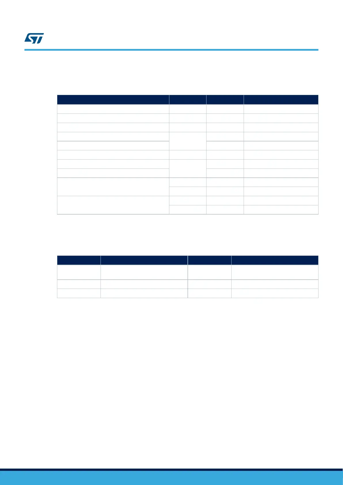
Hardware modifications are listed in Table 52.
Table 52. USB OTG HS function configuration
Signal name Pin name Setting
USB HS (CN8)
(1)
ULPI_D0 / I2S6_MCK PA3 JP9 [2-3]
ULPI_D1 / DFSDM12_CKOUT PB0 JP10 ON
ULPI_D5 / DFSDM12_DATIN1 PB12 JP19 [2-3]
ULPI_D7
PB5
JP16 ON
I2S6_SD JP18 OFF
ULPI_CK / I2S6_CK PA5 JP11 [2-3]
USB_OTG_HS_OVCR
PA4
R108 ON
I26_WS / DCMI_HSYNC JP7 OFF
USB_OTG_HS_PWR_EN
U7 CPEN SB12 ON
MFX_GPO4 SB32 OFF
USB_HS_PHY_RESET
MFX_GPO5 SB31 ON
NRST SB13 OFF
1. The default configuration is in bold.
8.4.4 Interface
Table 53. USB OTG HS Micro-AB connector CN8
Pin number Description Pin number Description
1
VBUS (From STMPS2151STR or to
USB3320C-EZK)
4 ID (From USB3320C-EZK)
2 D- (From USB3320C-EZK) 5 GND
3 D+ (From USB3320C-EZK) - -
8.5 DFSDM STMP2 and PT100 monitoring
8.5.1 Description
Two STMPS2 ICs are connected to STM32H7B3LIH6QU DFSDM1_2 interface:
• U36 is transmitting analog data from a power metering jumper (JP1) to DFDSM_DATIN1.
• U37 is transmitting temperature analog data from a PTS (R200) to DFDSM_DATIN5.
8.5.2 Operating voltage
STM32H7B3LIH6QU DFSDM STMPS2 and PT100 monitoring interfaces can only be at 3.3 V on this board. The
power supply (VCC) of both STPMS2L-PUR (U36 and U37) is “3V3_SW”. Take care to control this power supply
or use one of the hardware configurations to force it “always ON” (Refer to Section 8.5.2 )
8.5.3 Limitations and hardware configuration
Limitations: DFSDM Audio and USB HS
Hardware modifications:
• Fit R201, R202, R205, R208, and R33.
• Remove the MB1299 DFSDM audio module.
UM2662
DFSDM STMP2 and PT100 monitoring
UM2662 - Rev 1
page 57/95