If a deadlock occurs because of a mismatch between hardware and firmware PWR settings (SMPS/LDO), the
user can recover the board by applying the following procedure:
1. Power off the board.
2. Set SW1 (BOOT0) to 1 (system memory).
This changes the BOOT0 pin to 1 instead of 0, thus changing the device boot address to boot address 1
and making the bootloader start in System memory. This avoids starting firmware in the user Flash with a
wrong SMPS/LDO configuration versus the hardware board configuration.
3. Power on the board and connect using STM32CubeProgrammer (STM32CubeProg).
4. Erase the user Flash.
5. Power off the board and set SW1 to 0.
6. The board is recovered and can be used normally with matching firmware PWR.
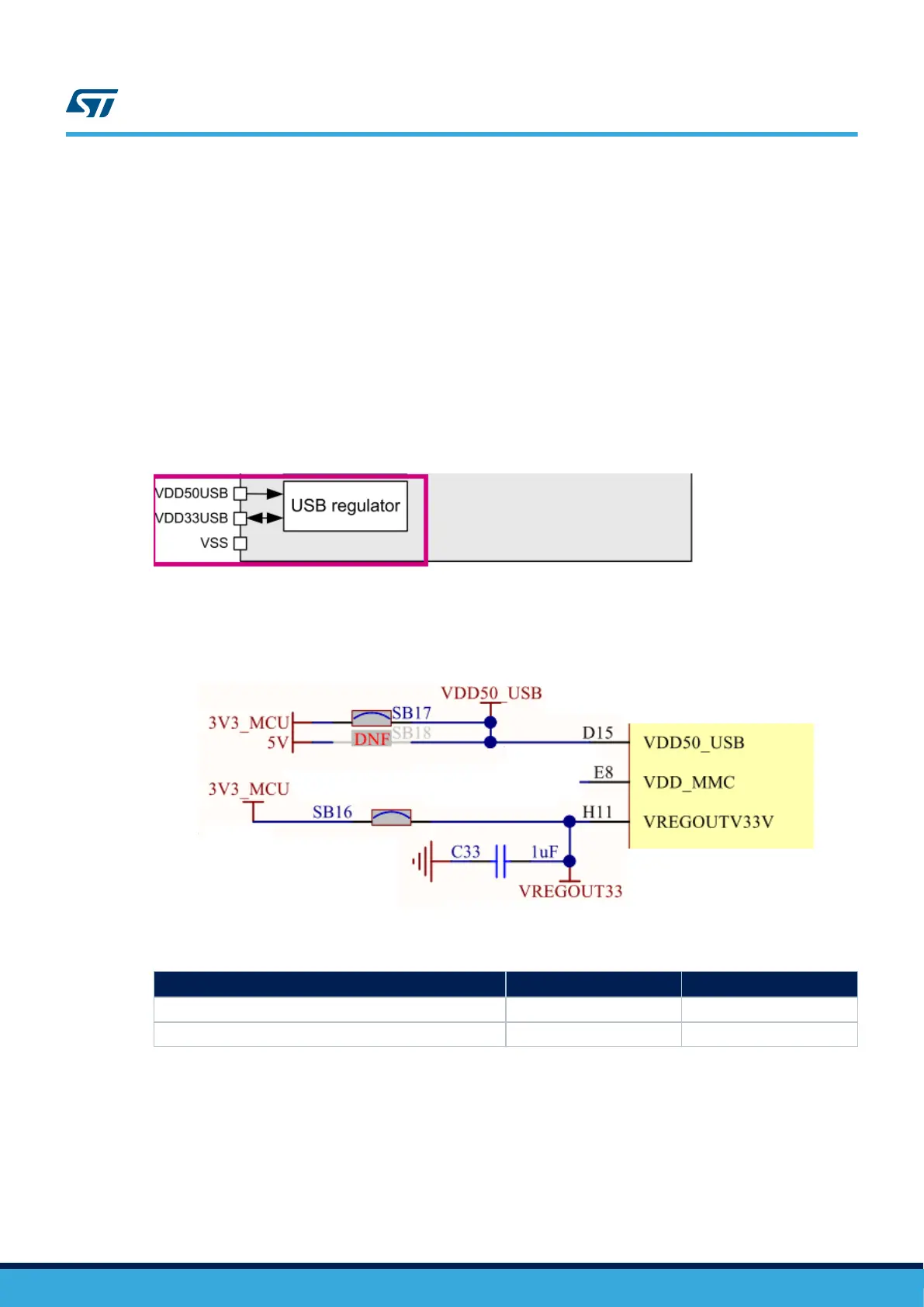
6.3.4 Board power supply - VDD50_USB and VREGOUTV33V
Figure 15. MCU Power: USB regulator
The USB power sources to STM32H7B3LIH6QU microcontroller can be selected by setting solder bridges as
shown in Table 11:
Figure 16. VDD50_USB and VREGOUTV33V schematic (Page 21)
Table 11. USB power sources
Power mode
(1)
Mount Unmount
External USB supply SB16, SB17 SB18
USB regulator supply SB18 SB16, SB17
1. The default setting is in bold.
UM2662
Power supply
UM2662 - Rev 1
page 22/95