Table 59. CN10 (Left) MB1242 pin-out
Pin number Description Pin number Description
1,4,8,9 NC 7 CANH
2 CANL 3,5,6 GND
8.8 Motor control
8.8.1 Description
Motor-control functions can be accessed:
• Either through the 17x2 legacy connector CN1,
• or through the 10x2 DFSDM connector CN4.
8.8.2 Operating voltage
The STM32H7B3LIH6QU motor-control interfaces (Such as GPIO, PWM, and ADC) can only be at 3.3 V on this
board.
8.8.3 Limitations and hardware configuration
Limitations with primary functions: USB FS, Wi‑Fi
®
, SD card 1, camera, audio I2S6, SDRAM, OCSPI1
Limitations with secondary functions: audio SAI, USB HS, NOR, SRAM, TRACE, KEY WKUP, MCO1,
3V3_SW_ENABLE and 1V8_SW_ENABLE
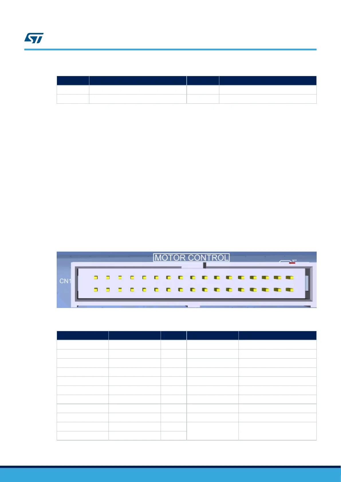
8.8.4 Interface
Figure 34. Motor-control legacy connector CN1
Table 60. Motor-control legacy connector CN1 (17x2)
Pin name Fitted Not fitted MCU function Motor-control function
PF12 R72 R326 ADC1_INP6 BUS VOLTAGE
PC0 R253 R255 ADC12_INP10 PHASE A CURRENT
PC1 R210 R216 ADC12_INP11 PHASE B CURRENT
PC4 R277 R281 ADC12_INP4 PFC INDUCTOR CURRENT
PA7 R67 R322 ADC12_INP7 PHASE C CURRENT
PC5 R282 R286 ADC12_INP8 PFC VAC
PC3_C R219 ADC2_INP1 HEATSINK TEMPERATURE
MFX_GPO6 SB33 / R130 R129 GPIO1 ICL SHUT OUT
MFX_GPO7 SB30 / R99 R100 GPIO2 DISSIPATIVE BREAK
PD4 R367 R368
INT_JOY_DOWN JOYSTICK DOWN
PA4 - JP7
UM2662
Motor control
UM2662 - Rev 1
page 62/95

 Loading...


