7.2.2 Operating voltage
DFSDM microphone module supports only 3.3 V.
Make sure to supply 3.3 V on VDDMMC (Refer to Section 6.3.5 ).
7.2.3 Limitations and hardware configuration
Limitations with primary functions: camera (Refer to jumper configuration in Table 27)
Limitations with secondary functions: USB HS and NOR Flash
Hardware modifications are listed in Table 27:
Table 27. Hardware configuration for DFSDM microphones module
Signal name Pin name Setting
DFSDM
(1)
DFSDM1_2_DATIN1 PB12 JP19 [1-2]
DFSDM1_DATIN3 PC7 JP35 [2-3]
DCMI_D1 - R113
OFF
(2)
MEMS_LED
PB8
(3)
R120 ON
DCMI_D6 R110
OFF
(2)
DFSDM1_DATIN5 PB6 R33 OFF
DFSDM1_CKOUT PB0 JP10 OFF
1. The default setting is in bold.
2. Remove to avoid stub if necessary.
3. PB8 signal is supplied by VDDMMC. Make sure to supply 3.3V on VDDMMC (Refer to Section 6.3.5
Note:
I
2
C address of CS42L51-CNZ is 0x94 (AD0=0).
7.2.4 Interface
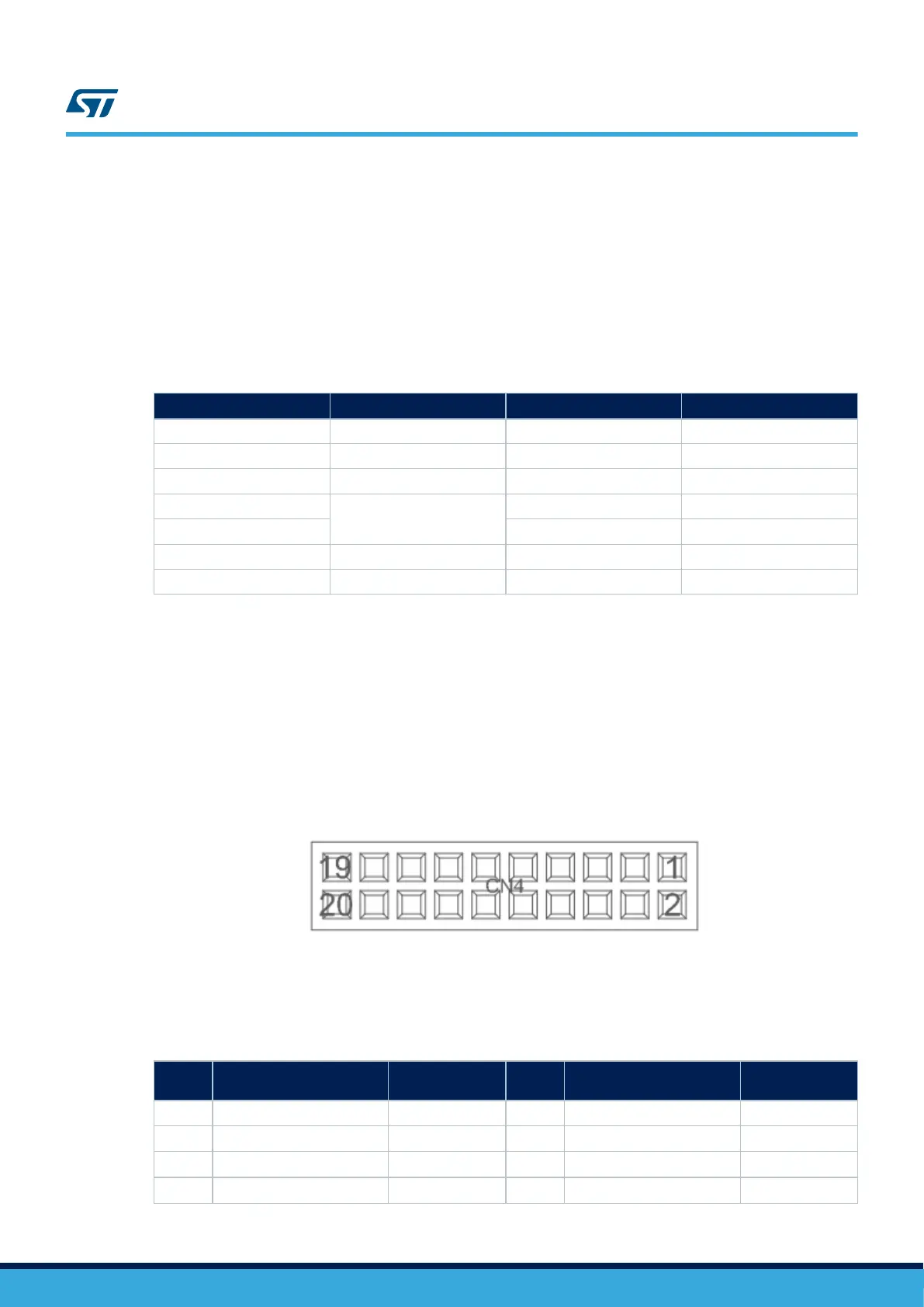
Figure 24. MEMS microphone module and motor Control module connector CN4
Table 28. MEMS microphone module MB1299 and motor control module connector CN4
Pin
number
Description Pin connection
Pin
number
Description Pin connection
1 GND GND 2 3V3_AO 3V3_AO
3
DFSDM1_2_CKOUT
(1)
PB0 4
DFSDM1_2_CKOUT
(1)
PB0
5
DFSDM1_DATIN3
(1)
PC7 6
DFSDM1_2_DATIN1
(1)
PB12
7 DFSDM1_DATIN5 PB6 8
DFSDM1_DATIN7
(1)
PB9
UM2662
DFSDM microphones module (MB1299)
UM2662 - Rev 1
page 34/95