6.5.3 Hardware configuration
VCP ST-LINK UART on PB14/PB15 (Default configuration)
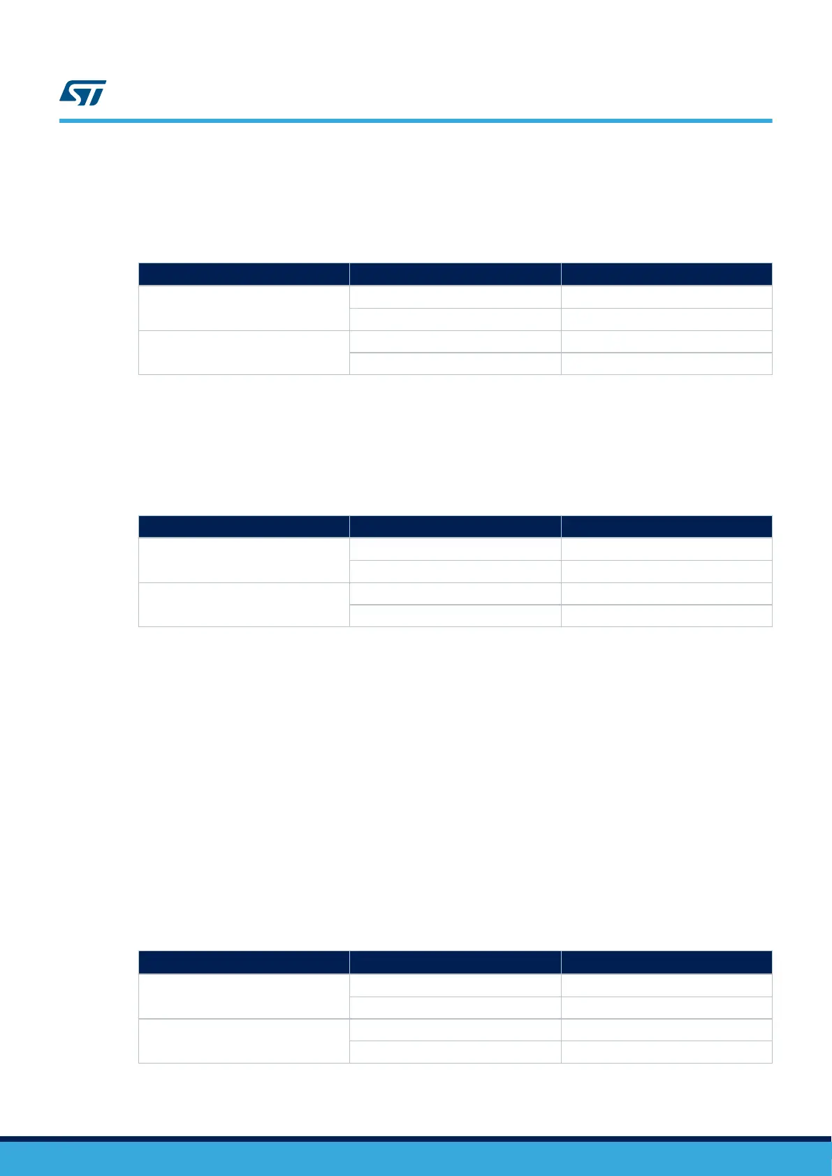
Table 20. STLINK-V3E VCP UART (PB14/P15: Default configuration)
Pin name Setting
STLINK-V3E VCP
(1)
PB14 (MCU TX)
JP21 / SB42 ON
JP39 OFF
PB15 (MCU RX)
JP20 / SB41 ON
JP40 OFF
1. The default setting is in bold.
VCP ST-LINK RS-232 UART on PA2/PA3
Important:
Audio I2S6, USB HS, and motor control cannot be used with VCP UART PA2/PA3.
Table 21. STLINK-V3E VCP UART (PA2/PA3: Compatible with bootloader)
Pin name Setting STLINK-V3E VCP (Bootloader)
PA2 (MCU TX)
JP21 OFF
JP39 / SB42 ON
PA3 (MCU RX)
JP20 OFF
JP40 / SB41 ON
6.6 RS-232 UART
6.6.1 Description
RS-232 communication is supported by D-type 9-pins RS-232 connector CN9, which is connected to PB14/PB15
(Default configuration) or PA2/PA3 (Compatible with bootloader) pins of STM32H7B3LIH6QU on the
STM32H7B3I-EVAL Evaluation board through ST3241EBPR RS-232 transceiver U9.
The Bootloader_RESET and Bootloader_BOOT0 signals are added on RS-232 connector CN9 for ISP support.
6.6.2 Operating voltage
The STM32H7B3LIH6QU UART interface can only be at 3.3 V on this board.
6.6.3 Hardware configuration
RS-232 UART on PB14/PB15 (Default configuration)
Hardware modifications are listed in Table 22:
Table 22. RS-232 UART (PB14/P15: Default configuration)
Pin name
Setting
STLINK-V3E VCP
(1)
PB14 (MCU TX)
JP21 / SB50 ON
JP39 / SB42 OFF
PB15 (MCU RX)
JP20 / SB49 ON
JP40 / SB41 OFF
1. The default setting is in bold.
UM2662
RS-232 UART
UM2662 - Rev 1
page 29/95