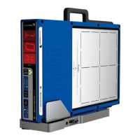
QA BEAMCHECKER™ PLUS 61
For TomoTherapy, it is advantageous to CT the QA BeamChecker Plus so that the center of the
image is aligned with the BBs and allow the device to eventually be setup by initially setting
the green lasers to these BBs. In this way, setup can be kept constant for both static and
dynamic procedures. Since the red laser positions can be set to any desired location as part of
the treatment planning process, using the laser control on the ROI panel, the red lasers can be
moved a known distance from the green lasers that can eventually be checked by using the
ruled markings on the QA BeamChecker Plus.
The treatment plan is intended to deliver dose to the detectors in the QA BeamChecker Plus,
thus requiring that contours are drawn to encompass the detectors. As a suggestion, five
separate contours can be drawn around the left, center, right, top and bottom detectors with
different doses prescribed to each of these contours. However, any size and number of
contours that encompass the detector will work. Top and bottom chamber contours are not
required for TomoTherapy planning as they are not used in either static or dynamic mode
testing.
NOTE: Be careful when using auto contouring techniques as filters placed above and below
the energy detection chambers within the QA BeamChecker Plus (See Appendix D: Chamber
Location Diagram) can create heavy artifacts within a kV CT image. These artifacts can affect
the volume perceived by the planning software and slightly affect the accuracy of the dose
calculation. However, the QA BeamChecker Plus is used only as a constancy check. As long as
the same plan is delivered, and in the same manner daily, the device will determine if the
measurement is out of specification as compared to a baseline.
When performing TomoTherapy measurements, this reference image will be fused to the
MVCT image taken after the initial positioning of the QA BeamChecker Plus. The exact steps
will depend on the specific CT machine and treatment planning software used, and future
developments within the TomoTherapy software.
After image acquisition and contouring, image(s) and contours can be sent to the treatment
planning system for planning.
13.3 TomoTherapy System Planning
Static Mode
For the Static mode, a procedure can be created on the Operator’s Station that irradiates the
device with a static 1, 2.5 or 5 cm x 40 cm field, with only the MLCs modulating as the
treatment couch moves past the treatment beam. Known as the TomoDirect™ mode, the
gantry is held fixed at 0°. Refer to the appropriate Treatment Planning and Treatment
Delivery System documentation from Accuray for specific information on developing
treatment plans of this variety.
Dynamic Mode
For the Dynamic Mode, a plan or plans can be created using the TomoTherapy Treatment
Planning Software. Multiple plans can be created and tested for each jaw width, but 2.5 cm is
the most common. Ideally, the plan developed challenges the system in reproducibility,
thereby potentially identifying any delivery issues in the QA routine. A different dose
prescribed to the each of the chambers is one possible technique.

 Loading...